Lexus NX: Customize Parameters
CUSTOMIZE PARAMETERS
CUSTOMIZE HEADUP DISPLAY SYSTEM
(a) Customizing with the Techstream
(1) Connect the Techstream to the DLC3.
(2) Turn the power switch on (IG).
(3) Turn the Techstream on.
(4) Enter the following menus: Customize Setting / Display.
(5) Select the setting by referring to the table below.
NOTICE:
Be sure to record the current value before customizing.
Display| Tester Display | Description | Default | Setting | ECU |
|---|---|---|---|---|
| Projection Adjustment (Tilt) | Headup display image calibration (Tilt calibration) | Default | 1000000:Clockwise (Hi),0100000:Clockwise (Mid),0010000:Clockwise (Lo),0001000:Default,0000100:Anti-Clockwise (Lo),0000010:Anti-Clockwise (Mid),0000001:Anti-Cloc**cut** | Meter mirror sub-assembly |
(b) Customize
(1) Operate the headup display switch assembly to set the display function to ON or OFF.
HINT:
The audio display function can be customized when vehicle speed is below 8 km/h (5 mph) (the audio display function switches to normal control when the vehicle speed is 8 km/h [5 mph] or more).
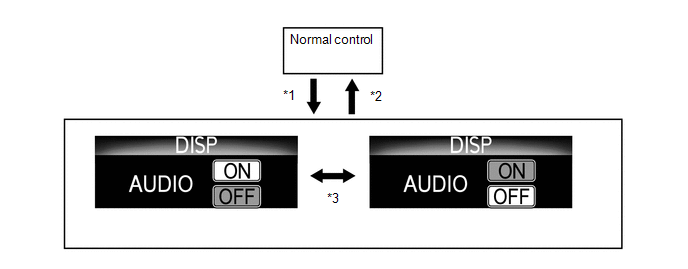
| *1 | Switch is pressed and held | *2 | Switch is pressed and held, or is not operated for 3 seconds |
| *3 | Switch is pressed briefly | - | - |
READ NEXT:
 How To Proceed With Troubleshooting
CAUTION / NOTICE / HINT HINT:
Use the following procedure to troubleshoot the headup display system.
*: Use the Techstream.
PROCEDURE 1. VEHICLE BROUGHT TO WORKSHOP
NEXT
Problem Symptoms Table
PROBLEM SYMPTOMS TABLE HINT:
Use the table below to help determine the cause of problem symptoms. If multiple suspected areas are listed, the potential causes of the symptom are listed in order of
Terminals Of Ecu
TERMINALS OF ECU HEADUP DISPLAY (METER MIRROR SUB-ASSEMBLY) (a) Measure the voltage and resistance according to the value(s) in the table below. Terminal No. (Symbol) Wiring Color Terminal Des
SEE MORE:
Fail-safe Chart
FAIL-SAFE CHART FAIL-SAFE FUNCTION (w/ Rain Sensor) (a) When the windshield wiper switch assembly is in the AUTO position and any of the following conditions are met, intermittent operation according to the sensitivity setting is performed. (1) Rain sensor output malfunction (b) When the windshield
Wireless-linked Return Function does not Operate
DESCRIPTION When a door is unlocked using the wireless unlock function, the certification ECU (smart key ECU assembly) sends a key ID signal to the main body ECU (multiplex network body ECU). When a door is unlocked using the entry unlock function, the certification ECU (smart key ECU assembly) send
