Lexus NX: Data List / Active Test
DATA LIST / ACTIVE TEST
DATA LIST
NOTICE:
- In the table below, the values listed under "Normal Condition" are reference values. Do not depend solely on these reference values when deciding whether a part is faulty or not.
- When using the Techstream with the power switch off, connect the Techstream to the DLC3 and turn a courtesy light switch on and off at intervals of 1.5 seconds or less until communication between the Techstream and the vehicle begins. Then select the vehicle type under manual mode and enter the following menus: Body Electrical / Smart Access. While using the Techstream, periodically turn a courtesy light switch on and off at intervals of 1.5 seconds or less to maintain communication between the Techstream and the vehicle.
HINT:
Using the Techstream to read the Data List allows the values or states of switches, sensors, actuators and other items to be read without removing any parts. This non-intrusive inspection can be very useful because intermittent conditions or signals may be discovered before parts or wiring is disturbed. Reading the Data List information early in troubleshooting is one way to save diagnostic time.
(a) Connect the Techstream to the DLC3.
(b) Turn the power switch on (IG).
(c) Turn the Techstream on.
(d) Enter the following menus: Body Electrical / Smart Access, Main Body, Power Source Control or Combination Meter / Data List.
(e) Read the Data List according to the display on the Techstream.
Body Electrical > Smart Access > Data List| Tester Display | Measurement Item | Range | Normal Condition | Diagnostic Note |
|---|---|---|---|---|
| D-Door Touch Sensor | Driver door touch sensor (unlock sensor)* | ON or OFF | ON: Driver door touch sensor (unlock sensor) touched OFF: Driver door touch sensor (unlock sensor) not touched |
|
| P-Door Touch Sensor | Front passenger door touch sensor (unlock sensor)* | ON or OFF | ON: Front passenger door touch sensor (unlock sensor) touched OFF: Front passenger door touch sensor (unlock sensor) not touched |
|
| Dr-Door Touch Sensor | Rear door LH touch sensor (unlock sensor)* | ON or OFF | ON: Rear door LH touch sensor (unlock sensor) touched OFF: Rear door LH touch sensor (unlock sensor) not touched |
|
| Pr-Door Touch Sensor | Rear door RH touch sensor (unlock sensor)* | ON or OFF | ON: Rear door RH touch sensor (unlock sensor) touched OFF: Rear door RH touch sensor (unlock sensor) not touched |
|
| D-Door Trigger Switch | Driver door touch sensor (lock sensor)* | ON or OFF | ON: Driver door touch sensor (lock sensor) touched OFF: Driver door touch sensor (lock sensor) not touched |
|
| P-Door Trigger Switch | Front passenger door touch sensor (lock sensor)* | ON or OFF | ON: Front passenger door touch sensor (lock sensor) touched OFF: Front passenger door touch sensor (lock sensor) not touched |
|
| Dr-Door Trigger Switch | Rear door LH touch sensor (lock sensor)* | ON or OFF | ON: Rear door LH touch sensor (lock sensor) touched OFF: Rear door LH touch sensor (lock sensor) not touched |
|
| Pr-Door Trigger Switch | Rear door RH touch sensor (lock sensor)* | ON or OFF | ON: Rear door RH touch sensor (lock sensor) touched OFF: Rear door RH touch sensor (lock sensor) not touched |
|
| Tr/B-Door Lock SW | Back door opener switch assembly (lock switch) | ON or OFF | ON: Back door opener switch assembly (lock switch) pressed OFF: Back door opener switch assembly (lock switch) not pressed |
|
| Tr/B-Door Unlock SW | Back door opener switch assembly (open switch) | ON or OFF | ON: Back door opener switch assembly (open switch) pressed OFF: Back door opener switch assembly (open switch) not pressed |
|
| Unmatched Vehicle-ID | Key No. (incorrect or correct) | Yes or No | Yes: Communication malfunction No: Communication normal | The vehicle ID registered in the vehicle and the vehicle ID registered in the electrical key transmitter sub-assembly are different (if a key from another vehicle is brought into the vehicle exterior detection area while the doors are locked, "Yes" is displayed for "Unmatched Vehicle-ID" in the Data List). Other potential causes:
|
| No Response | Communication response | Yes or No | Yes: Communication malfunction No: Communication normal | The vehicle IDs registered in the vehicle and electrical key transmitter sub-assembly match, but there is no response from the electrical key transmitter sub-assembly. (If the electrical key transmitter sub-assembly is not in the detection area or the transmitter battery is depleted resulting in a matching code not being detected when a lock switch or the power switch is pressed, etc., "Yes" is displayed for "No Response" in the Data List. If there is wave interference in the LF band that the vehicle uses for transmission or the RF band that the electrical key transmitter sub-assembly uses for transmission, "Yes" may be displayed for "No Response" in the Data List.) Other potential causes:
|
| Unmatch Code or Form | Code format (incorrect or correct) | Yes or No | Yes: Communication malfunction No: Communication normal | There is an error in the data sent from the electrical key transmitter sub-assembly (if there is wave interference in the RF band that the electrical key transmitter sub-assembly uses for transmission, "Yes" may be displayed for "Unmatch Code or Form", "No Response", "ID Code Difference(Resp)" and "C Code Difference" in the Data List). Other potential causes:
|
| Key Low Battery | Transmitter battery depleted | Yes or No | Yes: Transmitter battery depleted No: Transmitter battery not depleted | The electrical key transmitter sub-assembly sends voltage information to the certification ECU (smart key ECU assembly) when it is transmitting. The certification ECU (smart key ECU assembly) displays "Yes" for the "Key Low Battery" item of the Data List when this voltage information indicates 2.2 V or less. This Data List item should be checked when the electrical key transmitter sub-assembly is at room temperature (example: at -20°C (-4°F), "Yes" may be displayed even if the transmitter battery is new). |
| Power Save Cnt 10 Min. | Number of times power saving control is activated due to electrical key transmitter sub-assembly being in detection area for 10 minutes or more | 0 to 255 | Within range of 0 to 255 | If the electrical key transmitter sub-assembly is in a vehicle exterior detection area, communication is frequently performed between the vehicle and electrical key transmitter sub-assembly, resulting in an increase in transmitter battery power consumption. To prevent the transmitter battery from becoming fully depleted, if the electrical key transmitter sub-assembly is left in the detection area for 10 minutes or more, the smart access system with push-button start automatically deactivates the exterior detection area the electrical key transmitter sub-assembly is in. If the doors are locked/unlocked with a wireless operation or by the mechanical key, the system resumes operation. |
| Power Save Cnt 5 Days | Number of times power saving control 1 (vehicle exterior periodic signal transmission stop) is activated due to hybrid control system not being started for 5 days or more | 0 to 255 | Within range of 0 to 255 | - |
| Power Save Cnt 14 Days | Number of times power saving control 2 (lock/unlock sensor of front door outside handle assembly of front passenger door disabled) is activated due to hybrid control system not being started for 14 days or more | 0 to 255 | Within range of 0 to 255 | - |
| # Codes | Number of trouble codes | 0 to 255 | Number of stored DTCs displayed | - |
| ID Code Difference(Resp) | ID code (incorrect or correct) | Yes or No | Yes: Communication malfunction No: Communication normal | The ID code registered in the vehicle and the ID code registered in the electrical key transmitter sub-assembly are different (if there is wave interference in the RF band that the electrical key transmitter sub-assembly uses for transmission, "Yes" may be displayed for "Unmatch Code or Form", "No Response", "ID Code Difference(Resp)" and "C Code Difference" in the Data List). Other potential causes:
|
| C Code Difference | Challenge code (incorrect or correct) | Yes or No | Yes: Communication malfunction No: Communication normal | The electrical key transmitter sub-assembly sends a response code in response to the challenge code from the vehicle, but the response code is incorrect (if there is wave interference in the RF band that the electrical key transmitter sub-assembly uses for transmission, "Yes" may be displayed for "Unmatch Code or Form", "No Response", "ID Code Difference(Resp)" and "C Code Difference" in the Data List). Other potential causes:
|
| ID Code Difference | Wireless ID code (incorrect or correct) | Yes or No | Yes: Communication malfunction No: Communication normal | The ID code registered in the vehicle and the ID code registered in the electrical key transmitter sub-assembly are different. (If a wireless ID other than those for any of the registered electrical key transmitter sub-assemblies is detected, "Yes" is displayed for "ID Code Difference" in the Data List. If a wireless signal from the electrical key transmitter sub-assembly of another vehicle is detected, "Yes" is displayed for "ID Code Difference(Resp)" in the Data List.) Other potential causes:
|
| Immobiliser | Immobiliser system status determined by certification ECU | Set or Unset | Set: Immobiliser set (hybrid control system start prohibited) (power switch off) Unset: Immobiliser unset (hybrid control system start permitted) (power switch on (ACC) or on (IG)) | When the immobiliser system does not change to the unset state, this item can be used to determine if the cause is the certification ECU or ID code box. |
| Different Rolling Code | Rolling code (incorrect or correct) | Yes or No | Yes: Communication malfunction No: Communication normal | The rolling code registered in the vehicle and the rolling code registered in the electrical key transmitter sub-assembly are different Other potential causes:
|
| S Code Check | S code verification result | OK or NG | OK: S code verification result normal NG: S code verification result abnormal | Problems may be caused by the following:
|
| L Code Check | L code verification result | OK or NG | OK: L code verification result normal NG: L code verification result abnormal | Problems may be caused by the following:
|
| Unlock Request Receive | Status of steering unlock command from certification ECU (smart key ECU assembly) | OK or NG | OK: Certification ECU (smart key ECU assembly) sends steering unlock command (within 10 seconds of power switch turned on (ACC) or on (IG), or hybrid control system start operation performed) NG: Certification ECU (smart key ECU assembly) does not send steering unlock command (power switch not turned on (ACC) or on (IG), and hybrid control system start operation not performed) | - |
| Lock Request Receive | Status of steering lock command from certification ECU (smart key ECU assembly) | OK or NG | OK: Certification ECU (smart key ECU assembly) sends steering lock command (within 10 seconds of any door opened with shift lever in P and power switch off) NG: Certification ECU (smart key ECU assembly) does not send steering lock command (no door opened with shift lever in P and power switch off) | - |
| S Code Check(Past) | S code verification result (past) | OK or NG(Past) | OK: Verification result normal (past) NG(Past): Verification result abnormal (past) | - |
| L Code Check(Past) | L code verification result (past) | OK or NG(Past) | OK: Verification confirmed (past) NG(Past): Verification not confirmed (past) | - |
| Steering Lock | State of whether steering lock ECU (steering lock actuator assembly) has determined steering is locked | Set or Unset | Set: Steering locked Unset: Steering unlocked | If this item displays "Unset", the steering is not locked. |
| Steering Unlock | State of whether steering lock ECU (steering lock actuator assembly) determined steering is unlocked | Set or Unset | Set: Steering unlocked Unset: Steering locked | If this item displays "Unset", the steering is not unlocked (hybrid control system cannot be started). |
| B Code Difference | B code mismatch | Yes or No | Yes: Communication malfunction No: Communication normal | - |
| B Code | B code registration status | Regd or No Regd | Regd: B code registered correctly No Regd: B code not registered correctly | - |
| Door Unlock Mode2 | Door unlock mode | All or Driver | Customization status displayed | - |
| Ignition Available Area | Ignition available area | Front or All | Customization status displayed | - |
| Parking Wait Time | Parking wait time | 0.5s, 1.5s, 2.5s or 5s | Customization status displayed | - |
| B-Dr Opening Operation | Back door opening operation | Long,Twice or OFF | Customize setting status displayed | - |
| Touch Activation Over Threshold | Consecutive entry lock operation | Active or Not Active | Customization status displayed | - |
| Wireless Signal Encryption Support | Wireless signal encryption support | Yes or No | Yes: Wireless signal encryption supported No: Wireless signal encryption not supported | - |
| Key Low Battery Warning | Low transmitter battery warning | ON or OFF | Customization status displayed | - |
| Engine Start Indicator | Entry warning light lights | ON or OFF | Customization status displayed | - |
| Number of Registered Key Codes | Number of registered electrical key transmitter sub-assembly | 0 to 8 | Number of registered electrical key transmitter sub-assembly | Up to 7 electrical key transmitter sub-assemblies can be registered. |
| Short in Fr P Side Door Oscillators Circuit (Hist) | Short in front passenger door electrical key antenna circuit (history) | OK or NG(Hist) | OK: Front passenger door electrical key antenna circuit was normal NG(Hist): Front passenger door electrical key antenna circuit was abnormal | - |
| Short in D Side Door Oscillators Circuit (Hist) | Short in driver door electrical key antenna circuit (history) | OK or NG(Hist) | OK: Driver door electrical key antenna circuit was normal NG(Hist): Driver door electrical key antenna circuit was abnormal | - |
| Short in Front P Side Door Oscillators Circuit | Short in front passenger door electrical key antenna circuit | OK or NG | OK: Front passenger door electrical key antenna circuit is normal NG: Front passenger door electrical key antenna circuit is abnormal | - |
| Short in Driver Side Door Oscillators Circuit | Short in driver door electrical key antenna circuit | OK or NG | OK: Driver door electrical key antenna circuit is normal NG: Driver door electrical key antenna circuit is abnormal | - |
- *: Data from an actual vehicle provided for reference.
HINT:
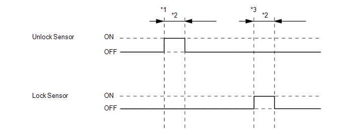
- *1: With power switch off, all doors closed, electrical key transmitter sub-assembly not inside vehicle and all doors locked, front door outside handle assembly (unlock sensor) touched.
- *2: Approximately 150 ms
- *3: With power switch off, all doors closed, electrical key transmitter sub-assembly not inside vehicle and all doors unlocked, front door outside handle assembly (lock sensor) touched.
| Tester Display | Measurement Item | Range | Normal Condition | Diagnostic Note |
|---|---|---|---|---|
| ACC SW | Power switch status | ON or OFF | ON: Power switch on (ACC) OFF: Power switch off | "ON" is displayed even though the power switch is on (IG). |
| IG SW | Power switch status | ON or OFF | ON: Power switch on (IG) OFF: Power switch off | "OFF" is displayed even though the power switch is on (ACC). |
| RR Door Courtesy SW | Rear door RH courtesy light switch | ON or OFF | ON: Rear door RH open OFF: Rear door RH closed | - |
| RL Door Courtesy SW | Rear door LH courtesy light switch | ON or OFF | ON: Rear door LH open OFF: Rear door LH closed | - |
| Back Door Courtesy SW | Back door courtesy light switch | ON or OFF | ON: Back door open OFF: Back door closed | - |
| FR Door Lock Pos | Front door RH unlock detection switch signal | UNLOCK or LOCK | UNLOCK: Front door RH unlocked LOCK: Front door RH locked | - |
| FR Door Courtesy SW | Front door RH courtesy light switch signal | ON or OFF | ON: Front door RH open OFF: Front door RH closed | - |
| FL Door Lock Pos | Front door LH unlock detection switch signal | UNLOCK or LOCK | UNLOCK: Front door LH unlocked LOCK: Front door LH locked | - |
| FL Door Courtesy SW | Front door LH courtesy light switch signal | ON or OFF | ON: Front door LH open OFF: Front door LH closed | - |
| RR-Door Lock Pos SW | Rear door RH unlock detection switch signal | ON or OFF | ON: Rear door RH unlocked OFF: Rear door RH locked | - |
| RL-Door Lock Pos SW | Rear door LH unlock detection switch signal | ON or OFF | ON: Rear door LH unlocked OFF: Rear door LH locked | - |
| Wireless Control | Wireless door lock function | ON or OFF | Customization status displayed | - |
| Hazard Answer Back | Hazard answer-back of entry function | ON or OFF | Customization status displayed | - |
| Open Door Warning | Open door warning | ON or OFF | Customization status displayed | - |
| Auto Lock Time | Automatic lock time | 30 s, 60 s or 120 s | Customization status displayed | - |
| Wirelss Buzzer Resp | Wireless buzzer answer-back of entry function | ON or OFF | Customization status displayed | - |
| Wireless Buzzer Vol | Wireless buzzer volume | Level7, Level6, Level5, Level4, Level3, Level2, Level1 or Level0 | Customization status displayed | - |
| Tester Display | Measurement Item | Range | Normal Condition | Diagnostic Note |
|---|---|---|---|---|
| Shift P Signal | Shift position P | ON or OFF | ON: Shift lever in P OFF: Shift lever not in P |
|
| Steering Unlock Switch | State of steering unlock sensor signal output from steering lock actuator assembly | ON or OFF | ON: Steering unlocked OFF: Steering locked |
|
| Stop Light Switch1 | State of brake pedal | ON or OFF | ON: Brake pedal depressed OFF: Brake pedal released |
|
| Start Switch1 | Power switch 1 status | ON or OFF | ON: Power switch pressed OFF: Power switch not pressed |
|
| Start Switch2 | Power switch 2 status | ON or OFF | ON: Power switch pressed OFF: Power switch not pressed |
|
| Vehicle Speed Signal | Vehicle being driven or stopped | Stop or Run | Stop: Vehicle stopped Run: Vehicle being driven at 5 km/h (3 mph) or more | - |
| Power Supply Condition | Power supply state | All OFF, ACC ON, IG ON or ST ON | All OFF: Power switch off (ACC and IG) ACC ON: Power switch on (ACC) IG ON: Power switch on (IG) ST ON: Sending hybrid control system start request signal | - |
| Tester Display | Measurement Item | Range | Normal Condition | Diagnostic Note |
|---|---|---|---|---|
| Vehicle Speed Meter | Vehicle speed | Min.: 0 km/h (0 mph), Max.: 255 km/h (158 mph) | Almost the same as actual vehicle speed | - |
ACTIVE TEST
HINT:
Using the Techstream to perform Active Tests allows relays, VSVs, actuators and other items to be operated without removing any parts. This non-intrusive functional inspection can be very useful because intermittent operation may be discovered before parts or wiring is disturbed. Performing Active Tests early in troubleshooting is one way to save diagnostic time. Data List information can be displayed while performing Active Tests.
(a) Connect the Techstream to the DLC3.
(b) Turn the power switch on (IG).
(c) Turn the Techstream on.
(d) Enter the following menus: Body Electrical / Smart Access or Main Body / Active Test.
(e) Perform Active Test according to the display on the Techstream.
Body Electrical > Smart Access > Active Test| Tester Display | Measurement Item | Control Range | Diagnostic Note |
|---|---|---|---|
| Overhead Tuner Power Supply ON | Door control receiver | OFF/ON | - |
| Power for P-Seat Sens | Front door outside handle (for front passenger door) | OFF/ON | - |
| Power for DR-Seat Sens | Rear door outside handle LH | OFF/ON | - |
| Power for PR-Seat Sens | Rear door outside handle RH | OFF/ON | - |
| Multi Channel SW | Door control receiver | CH1/CH2 | - |
| Tester Display | Measurement Item | Control Range | Diagnostic Note |
|---|---|---|---|
| Door Lock | Door lock motor | OFF/Unlock/Lock | - |
| D-Door Unlock | Driver door lock motor | OFF/ON | - |
| Trunk and Back-Door Open | Back door lock motor | OFF/ON | - |
| Wireless Buzzer | Wireless door lock buzzer | OFF/ON | - |
READ NEXT:
 Diagnostic Trouble Code Chart
DIAGNOSTIC TROUBLE CODE CHART Smart Access System with Push-button Start (for Entry Function) DTC No. Detection Item Link B27A1 Open in Driver Side Electrical Antenna Circuit B27
Operation History List
OPERATION HISTORY LIST NOTICE:
The cause of a malfunction is stored in the RAM or EEPROM in the certification ECU (smart key ECU assembly). As the cause of a malfunction stored in the RAM will be c
Open in Driver Side Electrical Antenna Circuit (B27A1)
DESCRIPTION The certification ECU (smart key ECU assembly) generates a request signal and transmits the signal to the front door outside handle assembly (for driver door) (electrical key antenna) at i
SEE MORE:
PBD Touch Sensor RH Circuit (B222B)
DESCRIPTION This DTC is output when the multiplex network door ECU detects a power back door sensor assembly RH touch sensor malfunction. DTC No. Detection Item DTC Detection Condition Trouble Area B222B PBD Touch Sensor RH Circuit Multiplex network door ECU detects power back door
Sound Quality is Bad Only when Disc is Played (Volume is Too Low)
CAUTION / NOTICE / HINT NOTICE: When replacing the radio receiver assembly, always replace it with a new one. If a radio receiver assembly which was installed to another vehicle is used, the following may occur:
A communication malfunction DTC may be stored.
The radio receiver assembly may not
