Lexus NX: Dcm(telematics Transceiver)
Components
COMPONENTS
ILLUSTRATION
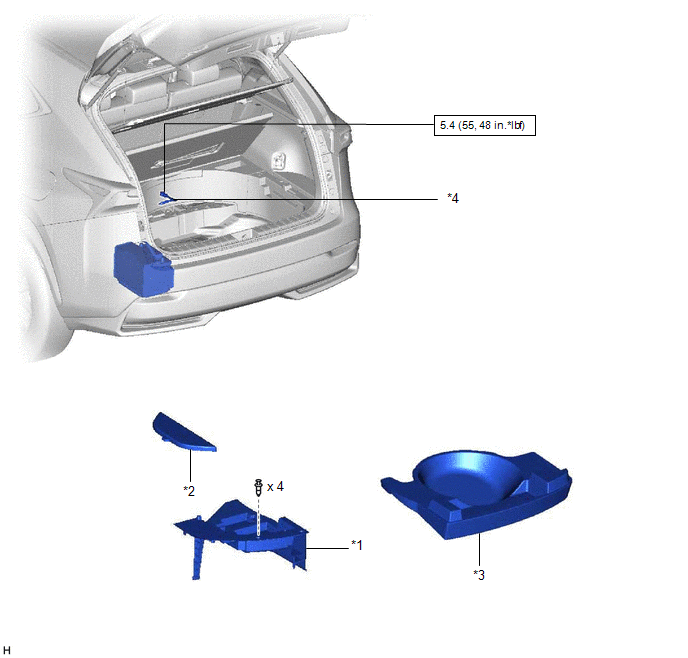
| *1 | DECK FLOOR BOX LH | *2 | NO. 3 DECK BOARD SUB-ASSEMBLY |
| *3 | REAR DECK FLOOR BOX | *4 | NEGATIVE AUXILIARY BATTERY TERMINAL |
.png) | N*m (kgf*cm, ft.*lbf): Specified torque | - | - |
ILLUSTRATION
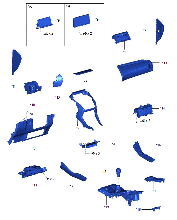
| *A | for 8 Inch | *B | for 10.3 Inch |
| *1 | AIR CONDITIONING CONTROL ASSEMBLY | *2 | CENTER INSTRUMENT CLUSTER FINISH PANEL ASSEMBLY |
| *3 | CONSOLE ARMREST ASSEMBLY | *4 | DCM (TELEMATICS TRANSCEIVER) WITH BRACKET |
| *5 | INSTRUMENT PANEL FINISH PLATE | *6 | INSTRUMENT SIDE PANEL LH |
| *7 | INSTRUMENT SIDE PANEL RH | *8 | LOWER NO. 1 INSTRUMENT PANEL FINISH PANEL |
| *9 | MULTI-DISPLAY ASSEMBLY WITH BRACKET | *10 | NO. 1 INSTRUMENT PANEL SAFETY PAD SUB-ASSEMBLY |
| *11 | NO. 1 INSTRUMENT PANEL UNDER COVER SUB-ASSEMBLY | *12 | NO. 1 SWITCH HOLE BASE |
| *13 | NO. 2 INSTRUMENT PANEL SAFETY PAD SUB-ASSEMBLY | *14 | RADIO RECEIVER ASSEMBLY WITH BRACKET |
| *15 | SHIFT LEVER KNOB SUB-ASSEMBLY | *16 | UPPER NO. 1 CONSOLE PANEL GARNISH |
| *17 | UPPER NO. 2 CONSOLE PANEL GARNISH | *18 | UPPER REAR CONSOLE PANEL |
| *19 | UPPER REAR CONSOLE PANEL SUB-ASSEMBLY | - | - |
ILLUSTRATION
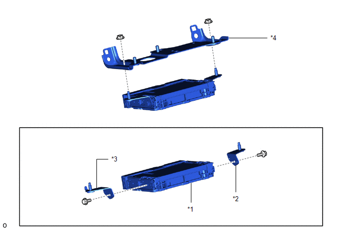
| *1 | DCM (TELEMATICS TRANSCEIVER) | *2 | NO. 1 TELEPHONE BRACKET |
| *3 | TELEPHONE BRACKET | *4 | NO. 2 TELEPHONE BRACKET |
READ NEXT:
 Precaution
PRECAUTION PRECAUTION FOR DISCONNECTING CABLE FROM NEGATIVE AUXILIARY BATTERY TERMINAL NOTICE: After the power switch is turned off, the radio receiver assembly records various types of memory and set
System Diagram
SYSTEM DIAGRAM
SEE MORE:
Panel Switches do not Function
CAUTION / NOTICE / HINT NOTICE: When replacing the radio receiver assembly, always replace it with a new one. If a radio receiver assembly which was installed to another vehicle is used, the following may occur:
A communication malfunction DTC may be stored.
The radio receiver assembly may not
Data List / Active Test
DATA LIST / ACTIVE TEST READ DATA LIST HINT: Using the Techstream to read the Data List allows the values or states of switches, sensors, actuators and other items to be read without removing any parts. This non-intrusive inspection can be very useful because intermittent conditions or signals may b
