Lexus NX: Diagnosis System
DIAGNOSIS SYSTEM
DIAGNOSIS FUNCTION
(a) When a malfunction occurs in the dynamic radar cruise control system, the system turns off the cruise control indicator. At the same time, a short buzzer sounds and "Cruise Control Malfunction Visit Your Dealer" is displayed in the multi-information display.
The hybrid vehicle control ECU or forward recognition camera store the DTC.
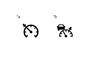
| *a | Cruise Control Indicator (Constant Speed Control Mode) |
| *b | Cruise Control Indicator (Vehicle-to-vehicle Distance Control Mode) |
NOTICE:
As data stored in the ECU will be cleared, do not remove any fuses or disconnect the cable from the negative (-) auxiliary battery terminal before the inspection is complete.
HINT:
When the system returns to normal, the warning message "Cruise Control Malfunction Visit Your Dealer" displayed on the multi-information display will be cleared.
READ NEXT:
 Dtc Check / Clear
DTC CHECK / CLEAR CHECK DTC (a) Connect the Techstream to the DLC3. (b) Turn the power switch on (IG). (c) Turn the Techstream on. (d) Enter the following menus: Powertrain / Radar Cruise1*1 or Radar
Fail-safe Chart
FAIL-SAFE CHART Constant Speed Control Mode: Condition Multi-information Display Master Warning Light Cruise Control Indicator Warning Buzzer When the following condition(s) occurs whil
Data List / Active Test
DATA LIST / ACTIVE TEST NOTICE:
In the table below, the values listed under "Normal Condition" are reference values. Do not depend solely on these reference values when deciding whether a part is f
SEE MORE:
Initialization
INITIALIZATION NOTICE:
The necessary procedures (adjustment, calibration, initialization or registration) that must be performed after parts are removed and installed, or replaced during headlight ECU sub-assembly LH removal/installation are shown below. Performed Work or System Condition Ne
How To Proceed With Troubleshooting
CAUTION / NOTICE / HINT HINT:
Use this procedure to troubleshoot the theft deterrent system.
*: Use the Techstream.
PROCEDURE 1. VEHICLE BROUGHT TO WORKSHOP
NEXT 2. CUSTOMER PROBLEM ANALYSIS (a) Interview the customer to confirm the trouble. Click here
