Lexus NX: Disassembly
DISASSEMBLY
CAUTION / NOTICE / HINT
HINT:
- Use the same procedure for the RH and LH side.
- The procedure listed below is for the LH side.
PROCEDURE
1. PRECAUTION
NOTICE:
After turning the power switch off, waiting time may be required before disconnecting the cable from the auxiliary battery negative (-) terminal.
Click here .gif)
2. REMOVE NO. 3 DECK BOARD SUB-ASSEMBLY
Click here
3. REMOVE REAR DECK FLOOR BOX
Click here
4. REMOVE DECK FLOOR BOX LH
Click here
5. DISCONNECT CABLE FROM NEGATIVE AUXILIARY BATTERY TERMINAL
CAUTION:
Wait at least 90 seconds after disconnecting the cable from the negative (-) battery terminal to disable the SRS system.
6. REMOVE REAR DOOR TRIM COVER LH
(a) Remove the rear door trim cover LH.
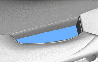
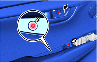
7. REMOVE REAR DOOR INSIDE HANDLE BEZEL PLUG LH
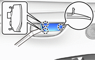
(a) Using moulding remover A, detach the 3 claws and remove the rear door inside handle bezel plug LH.
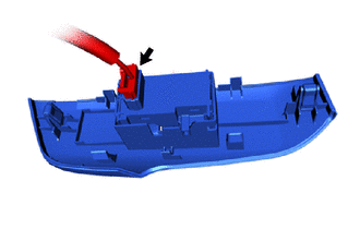
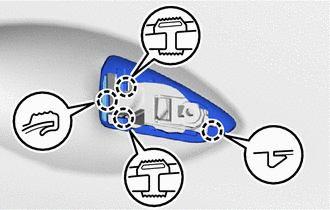
8. REMOVE REAR POWER WINDOW REGULATOR SWITCH ASSEMBLY WITH REAR DOOR ARMREST BASE PANEL
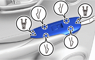
(a) Using moulding remover A, detach the 2 clips, 4 claws and remove the rear power window regulator switch assembly with rear door armrest base panel.
| (b) Disconnect the connector. |
|
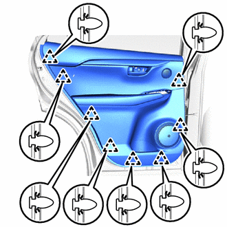
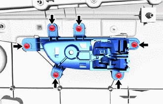
9. REMOVE REAR DOOR TRIM BOARD SUB-ASSEMBLY LH
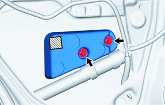
(a) Remove the screw labeled A.
.png) | Screw A |
.png) | Screw B |
.png) | Screw C |
(b) Remove the screw labeled B.
(c) Remove the screw labeled C.
| (d) Detach the 8 clips and remove the rear door trim board sub-assembly LH. |
|
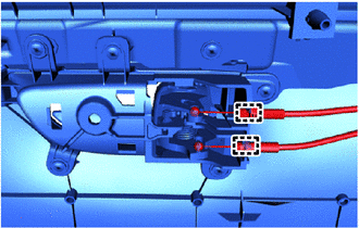
| (e) Disconnect the connector. |
|
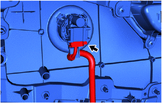
| (f) Detach the 2 clamps. |
|
(g) Disconnect the rear door lock remote control cable assembly LH and rear door inside locking cable assembly LH from the rear door trim board sub-assembly LH.
10. REMOVE REAR DOOR INSIDE HANDLE SUB-ASSEMBLY LH
| (a) Remove the 6 screws and rear door inside handle sub-assembly LH. |
|
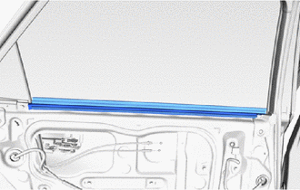
11. REMOVE REAR DOOR INNER GLASS WEATHERSTRIP LH
| (a) Remove the rear door inner glass weatherstrip LH. |
|
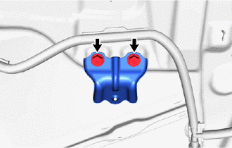
12. REMOVE REAR DOOR ARMREST SET BRACKET LH
| (a) Remove the 2 screws and rear door armrest set bracket LH. |
|
13. REMOVE REAR SPEAKER ASSEMBLY
Click here
14. REMOVE REAR NO. 2 SPEAKER ASSEMBLY
Click here
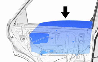
15. REMOVE REAR DOOR SERVICE HOLE COVER LH
| (a) Disconnect the 2 connectors. |
|
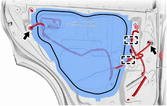
(b) Detach the 2 clamps, move the wire harness out of the way and remove the rear door service hole cover LH.
HINT:
Remove any remaining butyl tape from the door.
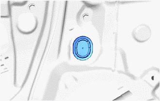
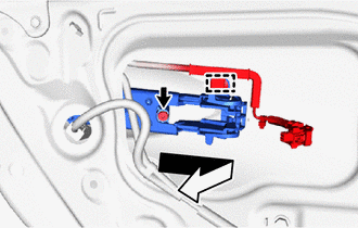
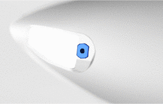
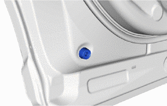
16. REMOVE REAR DOOR GLASS RUN LH
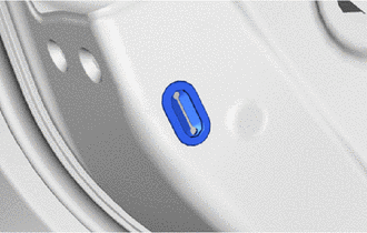
| (a) Remove the hole plug. |
|
(b) Temporarily install the power window regulator switch assembly with rear door armrest base panel.
(c) Connect the cable to the auxiliary battery negative (-) terminal.
| (d) Move the rear door window regulator so that the rear door glass bolts can be seen. |
|
(e) Disconnect the cable from the auxiliary battery negative (-) terminal.
NOTICE:
When disconnecting the cable, some systems need to be initialized after the cable is reconnected.
Click here
(f) Remove the power window regulator switch assembly with rear door armrest base panel.
| (g) Remove the rear door glass run LH. |
|
17. REMOVE REAR DOOR REAR LOWER WINDOW FRAME SUB-ASSEMBLY LH
(a) Remove the 2 bolts.
| | Bolt |
| | Screw |
(b) Remove the 2 screws and rear door rear lower window frame sub-assembly LH.
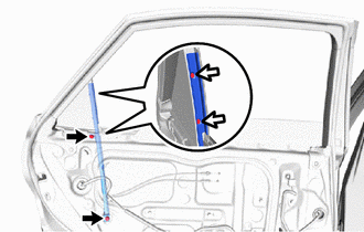
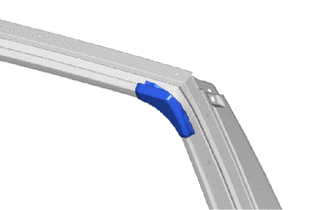
18. REMOVE REAR DOOR REAR GUIDE SEAL LH
(a) Lift up the weatherstrip and remove the 2 screws.
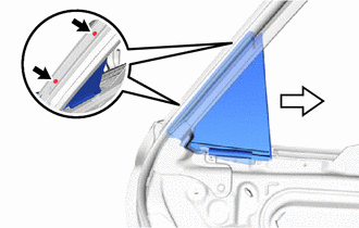
| | Screw |
| | Detaching Direction |
(b) Remove the rear door rear guide seal LH in the direction indicated by the arrow in the illustration.
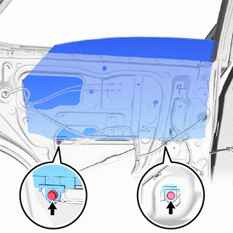
19. REMOVE REAR DOOR GLASS SUB-ASSEMBLY LH
| (a) Remove the 2 bolts. NOTICE: After the bolts are removed, do not allow the rear door glass to fall. |
|
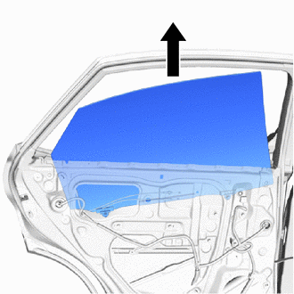
| (b) Remove the rear door glass sub-assembly LH in the direction indicated by the arrow in the illustration. NOTICE: Do not damage the rear door glass. |
|
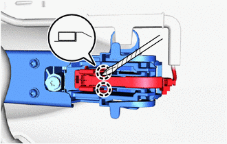
20. REMOVE REAR DOOR WINDOW REGULATOR SUB-ASSEMBLY LH
| (a) Loosen the temporarily bolt. NOTICE: Do not remove the temporarily bolt. If the temporarily bolt is removed, the rear door window regulator sub-assembly LH may fall and become damaged. |
|
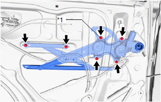
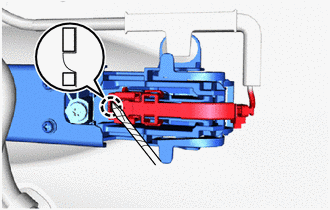
(b) Remove the 5 bolts and rear door window regulator sub-assembly LH.
(c) Remove the temporarily bolt from the rear door window regulator sub-assembly LH.
21. REMOVE REAR DOOR STIFFENER CUSHION LH
(a) Remove the 2 bolts, double-sided tape and rear door stiffener cushion LH.
.png) | Double-sided Tape |
NOTICE:
Remove any remaining tape from the door.
22. REMOVE REAR DOOR LOCK CHILD PROTECTION COVER
| (a) Remove the rear door lock child protection cover. |
|
23. REMOVE REAR DOOR LOCK ASSEMBLY LH
Click here
24. REMOVE REAR DOOR OUTSIDE HANDLE ASSEMBLY LH
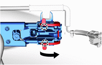
(a) Using a screwdriver, detach the 2 claws of the connector cover in the direction indicated and disconnect the connector cover.
HINT:
Tape the screwdriver tip before use.
| | Double-sided Tape |
(b) Using a screwdriver, detach the claw of the connector in the direction indicated and disconnect the connector.
HINT:
Tape the screwdriver tip before use.
| | Double-sided Tape |
| (c) Detach the 2 claws and remove the holder in the direction indicated by the arrow in the illustration. |
|
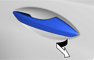
| (d) Remove the rear door outside handle assembly LH by sliding and pulling it in the direction indicated by the arrow in the illustration. |
|
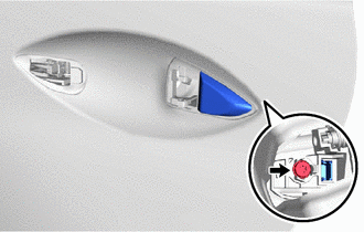
25. REMOVE REAR DOOR OUTSIDE HANDLE COVER LH
| (a) Using a T30 "TORX" socket wrench, loosen the screw and remove the rear door outside handle cover LH. |
|
26. REMOVE REAR DOOR FRONT OUTSIDE HANDLE PAD
| (a) Detach the 3 claws and remove the rear door front outside handle pad. |
|
27. REMOVE REAR DOOR REAR OUTSIDE HANDLE PAD
| (a) Detach the 4 claws and remove the rear door rear outside handle pad. |
|
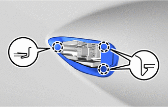
28. REMOVE REAR DOOR OUTSIDE HANDLE FRAME SUB-ASSEMBLY LH
| (a) Using a T30 "TORX" socket wrench, loosen the screw. |
|
(b) Detach the clamp and remove the rear door outside handle frame sub-assembly LH in the direction indicated by the arrow in the illustration.
29. REMOVE DOOR OUTSIDE HANDLE BUSH
| (a) Remove the door outside handle bush. |
|
30. REMOVE REAR DOOR CHECK ASSEMBLY LH
(a) Remove the bolt, 2 nuts and rear door check assembly LH.

| | Nut |
| | Bolt |
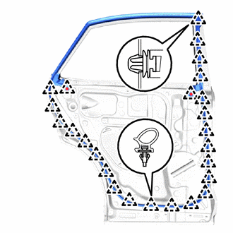
31. REMOVE REAR DOOR WEATHERSTRIP LH
| (a) Using a clip remover, detach the 25 clips and remove the rear door weatherstrip. |
|
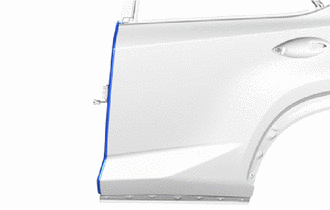
32. REMOVE REAR DOOR FRAME GARNISH LH
| (a) Remove the rear door frame garnish LH. |
|
33. REMOVE REAR DOOR PANEL CUSHION
| (a) Detach the rear door panel cushion. |
|
34. REMOVE REAR DOOR LOWER OUTSIDE MOULDING SUB-ASSEMBLY LH
Click here
35. REMOVE REAR DOOR UPPER OUTSIDE MOULDING PAD
Click here
36. REMOVE REAR DOOR NO. 2 WEATHERSTRIP LH
Click here
37. REMOVE REAR DOOR REAR UPPER OUTSIDE MOULDING LH
Click here
38. REMOVE REAR DOOR NO. 1 MOULDING PAD
Click here
39. REMOVE REAR DOOR REAR OUTSIDE MOULDING PAD
Click here
40. REMOVE NO. 2 MOULDING TAPE
Click here
41. REMOVE OUTSIDE MOULDING RETAINER
Click here
42. REMOVE REAR DOOR BELT MOULDING ASSEMBLY LH
Click here
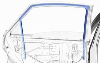
43. REMOVE REAR DOOR NO. 3 WEATHERSTRIP LH
| (a) Remove the rear door No. 3 weatherstrip LH. |
|
44. REMOVE REAR DOOR FRONT WINDOW FRAME MOULDING LH
Click here
45. REMOVE REAR DOOR UPPER WINDOW FRAME MOULDING LH
Click here
46. REMOVE REAR DOOR REAR WINDOW FRAME MOULDING LH
Click here
47. REMOVE NO. 1 BLACK OUT TAPE LH
Click here
48. REMOVE NO. 2 BLACK OUT TAPE LH
Click here
49. REMOVE NO. 3 BLACK OUT TAPE LH
Click here
READ NEXT:
 Inspection
INSPECTION PROCEDURE 1. INSPECT REAR DOOR OUTSIDE HANDLE ASSEMBLY LH (a) Check that the LED illuminates. (1) Apply 6.0 V (4 dry cell batteries in series) to each terminal and check the illumination
Adjustment
ADJUSTMENT CAUTION / NOTICE / HINT HINT:
Use the same procedure for the RH and LH sides.
The procedure listed below is for the LH side.
Centering bolts are used to mount the door hinge to the v
Reassembly
REASSEMBLY CAUTION / NOTICE / HINT HINT:
Use the same procedure for the RH and LH sides.
The procedure listed below is for the LH side.
A bolt without a torque specification is shown in the sta
SEE MORE:
Removal
REMOVAL CAUTION / NOTICE / HINT HINT:
Use the same procedure for the RH and LH sides.
The procedure listed below is for the LH side.
SST used when removing/installing the coil spring are shown as follows. *1 SST(09727-58100) *2 SST(09727-58130) *3 SST(09727-58030) *4 SST(0
Diagnostic Trouble Code Chart
DIAGNOSTIC TROUBLE CODE CHART ELECTRIC PARKING BRAKE SYSTEM DTC No. Detection Item Memory Note Link C1245 Deceleration Sensor Yes An electric parking brake system malfunction is displayed on the multi-information display. C13A0 Open Circuit in Power Source Circuit Y
