Lexus NX: Reassembly
REASSEMBLY
CAUTION / NOTICE / HINT
HINT:
- Use the same procedure for the RH and LH sides.
- The procedure listed below is for the LH side.
-
A bolt without a torque specification is shown in the standard bolt chart.
Click here
.gif)
PROCEDURE
1. REPAIR INSTRUCTION
Click here
2. INSTALL NO. 3 BLACK OUT TAPE LH
Click here
3. INSTALL NO. 2 BLACK OUT TAPE LH
Click here
4. INSTALL NO. 1 BLACK OUT TAPE LH
Click here
5. INSTALL REAR DOOR REAR WINDOW FRAME MOULDING LH
Click here
6. INSTALL REAR DOOR UPPER WINDOW FRAME MOULDING LH
Click here
7. INSTALL REAR DOOR FRONT WINDOW FRAME MOULDING LH
Click here
8. INSTALL REAR DOOR NO. 3 WEATHERSTRIP LH
HINT:
When installing the rear door No. 3 weatherstrip LH, heat the rear door panel using a heat light.
Standard:
| Item | Temperature |
|---|---|
| Rear Door Panel | 40 to 60°C (104 to 140°F) |
NOTICE:
Do not heat the rear door panel and rear door No. 3 weatherstrip LH excessively.
(a) Clean the rear door panel surface.
(1) Using a heat light, heat the rear door panel surface.
(2) Remove the double-sided tape from the rear door panel surface.
(3) Wipe off any tape adhesive residue with cleaner.
(b) Install a new rear door No. 3 weatherstrip LH.
(1) Using a heat light, heat the rear door panel surface.
(2) Remove the peeling paper from the face of the rear door No. 3 weatherstrip LH.
HINT:
After removing the peeling paper, keep the exposed adhesive free from foreign matter.
| (3) Install the rear door No. 3 weatherstrip LH as shown in the illustration. HINT: Press the rear door No. 3 weatherstrip LH firmly to install it. |
|
.png)
9. INSTALL REAR DOOR BELT MOULDING ASSEMBLY LH
Click here
10. INSTALL OUTSIDE MOULDING RETAINER
Click here
11. INSTALL NO. 2 MOULDING TAPE
Click here
12. INSTALL REAR DOOR REAR OUTSIDE MOULDING PAD
Click here
13. INSTALL REAR DOOR NO. 1 MOULDING PAD
Click here
14. INSTALL REAR DOOR REAR UPPER OUTSIDE MOULDING LH
Click here
15. INSTALL REAR DOOR NO. 2 WEATHERSTRIP LH
Click here
16. INSTALL REAR DOOR UPPER OUTSIDE MOULDING PAD
Click here
17. INSTALL REAR DOOR LOWER OUTSIDE MOULDING SUB-ASSEMBLY LH
Click here
18. INSTALL REAR DOOR PANEL CUSHION
(a) Install the rear door panel cushion.
19. INSTALL REAR DOOR FRAME GARNISH LH
(a) Install a new rear door frame garnish LH.
20. INSTALL REAR DOOR WEATHERSTRIP LH
(a) Attach the 25 clips to install the rear door weatherstrip LH.
21. INSTALL REAR DOOR CHECK ASSEMBLY LH
(a) Apply MP grease to the sliding area of the rear door check assembly LH.
(b) When reusing a bolt:
(1) Clean the threads of the bolt with non-residue solvent.
(2) Apply adhesive to the threads of the bolt.
Adhesive:
Toyota Genuine Adhesive 1324, Three Bond 1324 or equivalent.
(c) Install the rear door check assembly LH to the door panel with the 2 nuts.
Torque:
8.0 N·m {82 kgf·cm, 71 in·lbf}
(d) Install the rear door check assembly LH to the body panel with the bolt.
Torque:
27 N·m {275 kgf·cm, 20 ft·lbf}
22. INSTALL DOOR OUTSIDE HANDLE BUSH
(a) Install the door outside handle bush.
23. INSTALL REAR DOOR OUTSIDE HANDLE FRAME SUB-ASSEMBLY LH
(a) Apply MP grease to the sliding area of the rear door outside handle frame sub-assembly LH.
| (b) Temporarily install the rear door outside handle frame sub-assembly LH as shown in the illustration. |
|
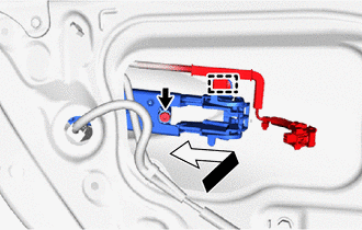
(c) Using a T30 "TORX" socket wrench, attach the clamp to install the rear door outside handle frame sub-assembly LH with the screw.
Torque:
4.0 N·m {41 kgf·cm, 35 in·lbf}
24. INSTALL REAR DOOR FRONT OUTSIDE HANDLE PAD
(a) Attach the 3 claws to install the rear door front outside handle pad.
25. INSTALL REAR DOOR REAR OUTSIDE HANDLE PAD
(a) Attach the 4 claws to install the rear door rear outside handle pad.
26. INSTALL REAR DOOR OUTSIDE HANDLE COVER LH
.png)
(a) Using a T30 "TORX" socket wrench, install the rear door outside handle cover LH with the screw.
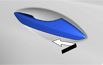
27. INSTALL REAR DOOR OUTSIDE HANDLE ASSEMBLY LH
| (a) Temporarily install the rear door outside handle assembly LH in the direction of the arrow shown in the illustration. |
|
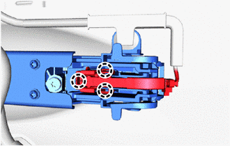
| (b) Attach the 2 claws to install the holder to the rear door outside handle assembly LH. |
|
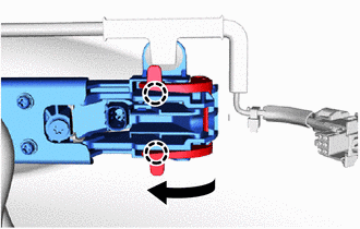
| (c) Connect the 3 claws to install the connector and connector cover. |
|
28. INSTALL REAR DOOR LOCK ASSEMBLY LH
Click here
29. INSTALL REAR DOOR LOCK CHILD PROTECTION COVER
(a) Install the rear door lock child protection cover.
30. INSTALL REAR DOOR STIFFENER CUSHION LH
(a) Clean vehicle installation surface.
.png) | Double-sided Tape |
(1) Remove any remaining double-sided tape from the vehicle installation surface.
(2) Clean the rear door panel sub-assembly installation surface with non-residue solvent.
(b) Remove the peeling paper on a new rear door stiffener cushion LH while making sure not to touch the adhesional surface.
(c) Install the rear door stiffener cushion LH with the 2 bolts.
Torque:
6.2 N·m {63 kgf·cm, 55 in·lbf}
(d) Press the rear door stiffener cushion LH against the door panel.
31. INSTALL REAR DOOR WINDOW REGULATOR SUB-ASSEMBLY LH
(a) Apply MP grease to the sliding and rotating areas of the rear door window regulator sub-assembly LH.
| (b) Temporarily install the temporarily bolt to the rear door window regulator sub-assembly LH. |
|
.png)
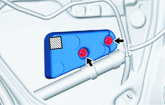
(c) Install the rear door window regulator sub-assembly LH with the 5 bolts, and then tighten the temporarily bolt.
Torque:
8.0 N·m {82 kgf·cm, 71 in·lbf}
HINT:
Tighten the bolts in the order shown in the illustration.
NOTICE:
Be careful not to drop the rear door window regulator as it may become damaged.
32. INSTALL REAR DOOR GLASS SUB-ASSEMBLY LH
(a) Temporarily install the power window regulator switch assembly with rear door armrest base panel.
(b) Connect the cable to the auxiliary battery negative (-) terminal.
(c) Move the rear door window regulator so that the rear door glass bolts can be seen.
(d) Disconnect the cable from the auxiliary battery negative (-) terminal.
NOTICE:
When disconnecting the cable, some systems need to be initialized after the cable is reconnected.
Click here
| (e) Insert the rear door glass sub-assembly LH as shown in the illustration. NOTICE: Do not damage the rear door glass sub-assembly. |
|
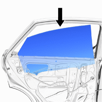
| (f) Install the rear door glass sub-assembly LH to the rear door window regulator sub-assembly LH with the 2 bolts. Torque: 8.0 N·m {82 kgf·cm, 71 in·lbf} |
|
.png)
(g) Install the hole plug.
33. INSTALL REAR DOOR REAR GUIDE SEAL LH
(a) Attach the rear door rear guide seal LH in the direction indicated by the arrow in the illustration.
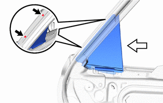
.png) | Screw |
.png) | Attaching Direction |
(b) Lift up the weatherstrip and install the rear door rear guide seal LH with the 2 screws.
34. INSTALL REAR DOOR REAR LOWER WINDOW FRAME SUB-ASSEMBLY LH
(a) Install the rear door rear lower window frame sub-assembly LH with the 2 screws.
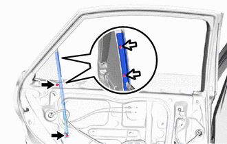
| | Bolt |
| | Screw |
(b) Install the 2 bolts.
Torque:
6.2 N·m {63 kgf·cm, 55 in·lbf}
35. INSTALL REAR DOOR GLASS RUN LH
(a) Install the rear door glass run LH.
36. INSTALL REAR DOOR SERVICE HOLE COVER LH
(a) Apply new butyl tape to the rear door panel.
(b) Pass each cable and connector through a new rear door service hole cover LH.
(c) Align the rear door service hole cover LH to the specified positions on the rear door panel sub-assembly and attach it.
HINT:
Securely install the front door service hole cover LH by attaching it without any wrinkles or air bubbles.
| (d) Attach the 2 clamps. |
|
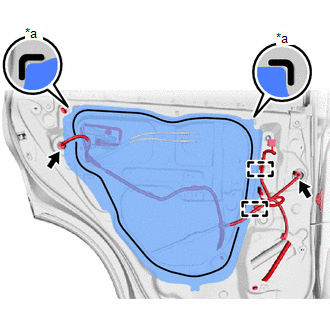
(e) Connect the 2 connectors.
37. INSTALL REAR SPEAKER ASSEMBLY
Click here
38. INSTALL REAR NO. 2 SPEAKER ASSEMBLY
Click here
39. INSTALL REAR DOOR ARMREST SET BRACKET LH
(a) Install the rear door armrest set bracket LH with the 2 screws.
40. INSTALL REAR DOOR INNER GLASS WEATHERSTRIP LH
(a) Install the rear door inner glass weatherstrip LH.
41. INSTALL REAR DOOR INSIDE HANDLE SUB-ASSEMBLY LH
(a) Install the rear door inside handle sub-assembly LH with the 6 screws.
42. INSTALL REAR DOOR TRIM BOARD SUB-ASSEMBLY LH
(a) Connect the rear door lock remote control cable assembly LH and rear door inside locking cable assembly LH.
(b) Attach the 2 clamps.
(c) Attach the 8 clips to install the rear door trim board sub-assembly LH.
(d) Connect the connector.
(e) Install the screw labeled A.
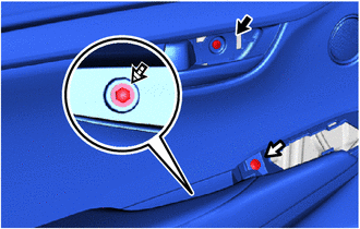
| | Screw A |
| | Screw B |
.png) | Screw C |
(f) Install the screw labeled B.
(g) Install the screw labeled C.
43. INSTALL REAR POWER WINDOW REGULATOR SWITCH ASSEMBLY WITH REAR DOOR ARMREST BASE PANEL
(a) Connect the connector.
(b) Attach the 4 claws, 2 clips to install the power window regulator switch assembly with rear door armrest base panel.
44. INSTALL REAR DOOR INSIDE HANDLE BEZEL PLUG LH
(a) Attach the 3 claws to install the rear door inside handle bezel plug LH.
45. INSTALL REAR DOOR TRIM COVER LH
(a) Install the rear door trim cover LH.
46. CONNECT CABLE TO NEGATIVE AUXILIARY BATTERY TERMINAL
47. INITIALIZATION AFTER RECONNECTING AUXILIARY BATTERY TERMINAL
Click here
HINT:
When disconnecting and reconnecting the auxiliary battery, there is an automatic learning function that completes learning when the respective system is used.
Click here
48. INSTALL DECK FLOOR BOX LH
Click here
49. INSTALL REAR DECK FLOOR BOX
Click here
50. INSTALL NO. 3 DECK BOARD SUB-ASSEMBLY
Click here
51. CHECK SRS WARNING LIGHT
Click here
52. PERFORM DIAGNOSTIC SYSTEM CHECK
Click here
53. INITIALIZE POWER WINDOW CONTROL SYSTEM
Click here
54. CHECK POWER WINDOW CONTROL SYSTEM
Click here
55. CHECK POWER DOOR LOCK CONTROL SYSTEM
Click here
READ NEXT:
 Rear Door Opening Trim Weatherstrip
ComponentsCOMPONENTS ILLUSTRATION *1 REAR DOOR OPENING TRIM WEATHERSTRIP LH *2 REAR DOOR SCUFF PLATE LH RemovalREMOVAL CAUTION / NOTICE / HINT HINT:
Use the same procedure for the RH
Relay
InspectionINSPECTION PROCEDURE 1. INSTALL RELAY BLOCK ASSEMBLY (a) Preparations for inspection (1) Connect the positive battery terminal to terminal 2 of the fuel lid opener relay and the negative
Reserve Lock Switch
ComponentsCOMPONENTS ILLUSTRATION *1 DOOR CONTROL SWITCH *2 PULL HANDLE RemovalREMOVAL PROCEDURE 1. REMOVE PULL HANDLE Click here 2. REMOVE DOOR CONTROL SWITCH (a) Detach the 2 cla
SEE MORE:
System Description
SYSTEM DESCRIPTION OUTLINE (Lexus Enform Remote) (a) Lexus Enform Remote enables the user to check the vehicle status and operate the vehicle from a remote location. (b) Lexus Enform Remote is available by installing a dedicated smartphone application after entering a service contract*.
*: Lexus
Odo/Trip Switch Malfunction
DESCRIPTION The ODO/TRIP display of the combination meter changes each time the trip switch is pressed. WIRING DIAGRAM CAUTION / NOTICE / HINT NOTICE: When replacing the combination meter assembly, make sure to replace it with a new one. PROCEDURE 1. READ VALUE USING TECHSTREAM (ODO/TRIP CHAN
