Lexus NX: Disassembly
DISASSEMBLY
CAUTION / NOTICE / HINT
NOTICE:
- When using a vise, place aluminum plates between the part and vise.
- When using a vise, do not overtighten it.
PROCEDURE
1. DISCONNECT FRONT NO. 2 AXLE INBOARD JOINT BOOT CLAMP LH
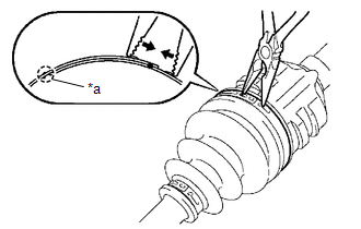
| *a | Claw Engagement |
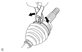
(a) Using needle-nose pliers, detach the claw engagement and disconnect the front No. 2 axle inboard joint boot clamp LH as shown in the illustration.
2. DISCONNECT FRONT NO. 2 AXLE INBOARD JOINT BOOT CLAMP RH
HINT:
Use the same procedure described for the LH side.
3. DISCONNECT FRONT AXLE INBOARD JOINT BOOT CLAMP LH
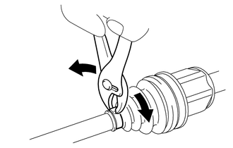
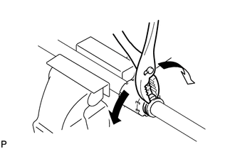
(a) Using pliers, grasp the front axle inboard joint boot clamp LH and move the front axle inboard joint boot clamp LH as shown in the illustration to disconnect the front axle inboard joint boot clamp LH from the front axle outboard joint boot.
4. DISCONNECT FRONT AXLE INBOARD JOINT BOOT CLAMP RH
HINT:
Use the same procedure described for the LH side.
5. DISCONNECT FRONT AXLE INBOARD JOINT BOOT
HINT:
Use the same procedure for the RH and LH sides.
(a) Disconnect the front axle inboard joint boot from the front drive inboard joint assembly.
6. REMOVE FRONT DRIVE INBOARD JOINT ASSEMBLY LH
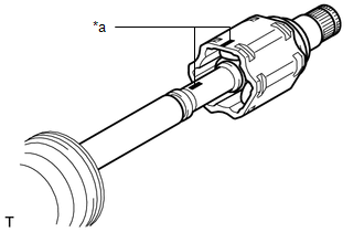
| *a | Matchmark |
(a) Remove any old grease from the front drive inboard joint assembly LH.
(b) Put matchmarks on the front drive inboard joint assembly LH and front drive outboard joint shaft assembly LH.
NOTICE:
Do not use a punch to make the matchmarks.
(c) Remove the front drive inboard joint assembly LH from the front drive outboard joint shaft assembly LH.
| (d) Using a snap ring expander, remove the shaft snap ring. |
|
| (e) Put matchmarks on the front drive outboard joint shaft assembly LH and tripod joint. NOTICE: Do not use a punch to make the matchmarks. |
|
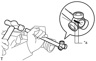
(f) Using a brass bar and hammer, remove the tripod joint from the front drive outboard joint shaft assembly LH.
NOTICE:
- Do not tap the rollers.
- Do not drop the tripod joint.
(g) Remove the front No. 2 axle inboard joint boot clamp, front axle inboard joint boot and front axle inboard joint boot clamp LH.
7. REMOVE FRONT DRIVE INBOARD JOINT ASSEMBLY RH
HINT:
Use the same procedure described for the LH side.
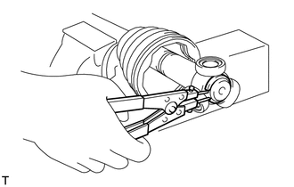
8. DISCONNECT FRONT DRIVE SHAFT DAMPER CLAMP LH
HINT:
Use the same procedure for each front drive shaft damper clamp LH.
(a) Using pliers, grasp the front drive shaft damper clamp LH and move the front drive shaft damper clamp LH as shown in the illustration to disconnect the front drive shaft damper clamp LH from the front drive outboard joint shaft assembly LH.
9. DISCONNECT FRONT DRIVE SHAFT DAMPER CLAMP RH
HINT:
Use the same procedure described for the LH side.
10. REMOVE FRONT DRIVE SHAFT DAMPER LH
(a) Remove the front drive shaft damper LH and 2 front drive shaft damper clamp LH from the front drive outboard joint shaft assembly LH.
11. REMOVE FRONT DRIVE SHAFT DAMPER RH
HINT:
Use the same procedure described for the LH side.
12. DISCONNECT FRONT NO. 2 AXLE OUTBOARD JOINT BOOT CLAMP LH
NOTICE:
Do not disassemble the outboard joint shaft assembly RH.
(a) Using pliers, grasp the front No. 2 axle outboard joint boot clamp LH and move the front No. 2 axle outboard joint boot clamp LH as shown in the illustration to disconnect the front No. 2 axle outboard joint boot clamp LH from the front axle outboard joint boot.
13. DISCONNECT FRONT AXLE OUTBOARD JOINT BOOT CLAMP LH
NOTICE:
Do not disassemble the outboard joint shaft assembly RH.
HINT:
Use the same procedure described for the front No. 2 axle outboard joint boot clamp LH.
14. REMOVE FRONT AXLE OUTBOARD JOINT BOOT (for LH Side)
NOTICE:
Do not disassemble the outboard joint shaft assembly RH.
(a) Remove the front axle outboard joint boot clamp LH, front axle outboard joint boot and front No. 2 axle outboard joint boot clamp LH from the front drive outboard joint shaft assembly LH.
(b) Remove any old grease from the front drive outboard joint shaft assembly LH.
15. REMOVE FRONT DRIVE SHAFT DUST COVER LH
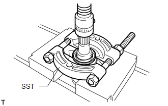
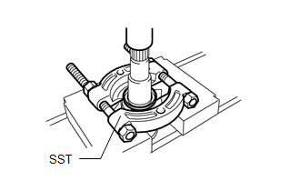
(a) Using SST and a press, remove the front drive shaft dust cover LH from the front drive inboard joint assembly LH.
SST: 09950-00020
NOTICE:
Do not drop the front drive inboard joint assembly LH.
16. REMOVE FRONT DRIVE SHAFT DUST COVER RH
| (a) Using SST and a press, remove the front drive shaft dust cover RH from the front drive inboard joint assembly RH. SST: 09950-00020 NOTICE: Do not drop the front drive inboard joint assembly RH. |
|
17. REMOVE FRONT DRIVE SHAFT BEARING (for RH Side)
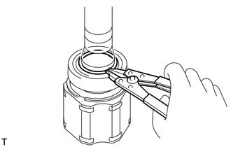
(a) Using a snap ring expander, remove the snap ring.
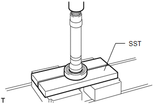
| (b) Using SST and a press, remove the front drive shaft bearing from the front drive inboard joint assembly RH. SST: 09527-10011 NOTICE: Do not drop the front drive inboard joint assembly RH. |
|
READ NEXT:
 Inspection
INSPECTION CAUTION / NOTICE / HINT NOTICE:
When using a vise, place aluminum plates between the part and vise.
When using a vise, do not overtighten it.
PROCEDURE 1. INSPECT FRONT DRIVE SHAFT
Reassembly
REASSEMBLY CAUTION / NOTICE / HINT NOTICE:
When using a vise, place aluminum plates between the part and vise.
When using a vise, do not overtighten it.
PROCEDURE 1. INSTALL FRONT DRIVE SHAFT
Installation
INSTALLATION PROCEDURE 1. INSTALL FRONT DRIVE SHAFT HOLE SNAP RING LH (a) Install a new front drive shaft hole snap ring LH. NOTICE:
Do not damage the spline of the front drive inboard joint assemb
SEE MORE:
System Diagram
SYSTEM DIAGRAM Tail, Stop, Headlight Circuit Turn Signal Circuit
Front Right Sensor Malfunction (C1AE4)
DESCRIPTION The front corner ultrasonic sensor (FR sensor) is installed to the front bumper. The clearance warning ECU assembly detects obstacles based on signals received from the front corner ultrasonic sensor (FR sensor). If the front corner ultrasonic sensor (FR sensor) has an open circuit or ot
