Lexus NX: Reassembly
REASSEMBLY
CAUTION / NOTICE / HINT
NOTICE:
- When using a vise, place aluminum plates between the part and vise.
- When using a vise, do not overtighten it.
PROCEDURE
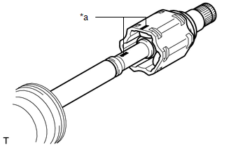
1. INSTALL FRONT DRIVE SHAFT BEARING (for RH Side)
| (a) Using SST and a press, press in the front drive inboard joint assembly RH until the new front drive shaft bearing contacts the edge of the front drive inboard joint assembly RH. SST: 09527-10011 SST: 09710-30012 09710-04081 NOTICE:
|
|
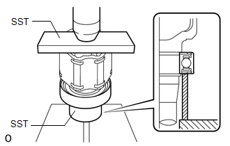
| (b) Using a snap ring expander, install a new snap ring. NOTICE: The snap ring should be installed completely. |
|
.png)
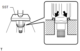
2. INSTALL FRONT DRIVE SHAFT DUST COVER LH
| (a) Using SST and a press, press in the front drive inboard joint assembly LH until the new front drive shaft dust cover LH contacts the edge of the front drive inboard joint assembly LH. SST: 09527-10011 NOTICE:
|
|
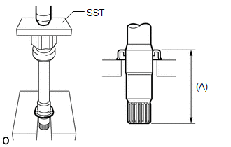
3. INSTALL FRONT DRIVE SHAFT DUST COVER RH
| (a) Using SST and a press, install a new front drive shaft dust cover RH to the front drive inboard joint assembly RH until the distance from the tip of the front drive inboard joint assembly RH to the front drive shaft dust cover RH reaches the specification as shown in the illustration. SST: 09527-10011 Standard distance (A): 115.5 to 116.5 mm (4.548 to 4.586 in.) NOTICE:
|
|
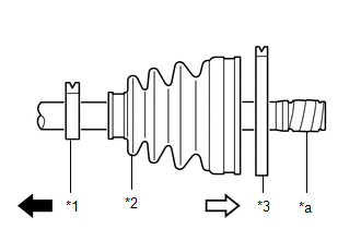
4. INSTALL FRONT AXLE OUTBOARD JOINT BOOT (for LH Side)
| (a) Before installing the front axle outboard joint boot, wrap the splines of the front drive outboard joint shaft assembly LH with protective tape to prevent the front axle outboard joint boot from being damaged. |
|
(b) Install new parts to the front drive outboard joint shaft assembly LH in the following order.
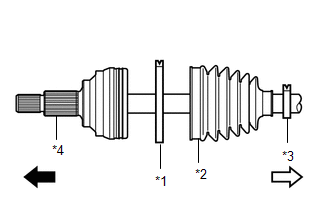
| *1 | Front No. 2 Axle Outboard Joint Boot Clamp LH |
| *2 | Front Axle Outboard Joint Boot |
| *3 | Front Axle Outboard Joint Boot Clamp LH |
| *4 | Front Drive Outboard Joint Shaft Assembly LH |
.png) | Outboard Joint Side |
.png) | Inboard Joint Side |
(1) Front No. 2 axle outboard joint boot clamp LH
(2) Front axle outboard joint boot
(3) Front axle outboard joint boot clamp LH
(c) Install the front axle outboard joint boot so that it is between the front No. 2 axle outboard joint boot clamp LH and front drive outboard joint shaft assembly LH.
(d) Temporarily install the front axle outboard joint boot clamp LH to the front axle outboard joint boot.
(e) Pack the front drive outboard joint shaft assembly LH and front axle outboard joint boot with grease from the boot kit.
Standard Grease Capacity:
164.0 to 184.0 g (5.78 to 6.49 oz)
(f) Install the front axle outboard joint boot to the groove of the front drive outboard joint shaft assembly LH.
NOTICE:
- Do not apply grease to the part of the front axle outboard joint boot that contacts the groove.
- Do not allow foreign matter to enter the front axle outboard joint boot.
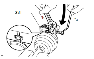
5. INSTALL FRONT NO. 2 AXLE OUTBOARD JOINT BOOT CLAMP LH
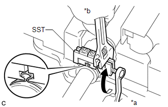
(a) Install SST to the front No. 2 axle outboard joint boot clamp LH, and then while pressing the front axle outboard joint boot, slightly tighten the SST bolt.
SST: 09521-24010
NOTICE:
- Correctly set the front No. 2 axle outboard joint boot clamp LH to the guide groove.
- Do not damage the front axle outboard joint boot.
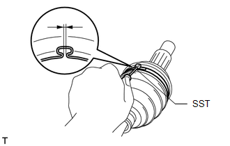
| (b) Tighten SST so that the front No. 2 axle outboard joint boot clamp LH is pinched. Standard Clearance: 0.5 to 1.5 mm (0.0197 to 0.0590 in.) NOTICE:
|
|
(c) Remove SST from the front No. 2 axle outboard joint boot clamp LH.
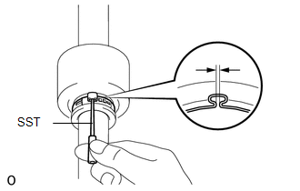
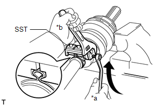
| (d) Using SST, measure the clearance of the front No. 2 axle outboard joint boot clamp LH. SST: 09240-00020 Standard Clearance: 0.5 to 1.5 mm (0.0197 to 0.0590 in.) NOTICE:
|
|
6. INSTALL FRONT AXLE OUTBOARD JOINT BOOT CLAMP LH
HINT:
Use the same procedure described for the front No. 2 axle outboard joint boot clamp LH.
7. INSTALL FRONT DRIVE SHAFT DAMPER LH
| (a) Install 2 new front drive shaft damper clamp LH and the front drive shaft damper LH onto the front drive outboard joint shaft assembly LH. |
|
(b) Adjust the position of the drive shaft damper LH so that the distance shown in the illustration is within the specified range.
Standard Distance (A):
214.0 to 220.0 mm (8.425 to 8.661 in.)
8. INSTALL FRONT DRIVE SHAFT DAMPER RH
HINT:
Use the same procedure described for the LH side.
9. INSTALL FRONT DRIVE SHAFT DAMPER CLAMP LH
HINT:
Use the same procedure for each front drive shaft damper clamp LH.
(a) Install SST to the front drive shaft damper clamp LH, and then while pressing the front drive shaft damper LH, slightly tighten the SST bolt.
SST: 09521-24010
NOTICE:
Correctly set the front drive shaft damper clamp LH to the guide groove.
| (b) Tighten SST so that the front drive shaft damper clamp LH is pinched. Standard Clearance: 0.5 to 1.5 mm (0.0197 to 0.0590 in.) NOTICE: When tightening SST, make sure the clearance of the front drive shaft damper clamp LH is within the standard clearance. |
|
(c) Remove SST from the front drive shaft damper clamp LH.
| (d) Using SST, measure the clearance of the front drive shaft damper clamp LH. SST: 09240-00020 Standard Clearance: 0.5 to 1.5 mm (0.0197 to 0.0590 in.) NOTICE:
|
|
10. INSTALL FRONT DRIVE SHAFT DAMPER CLAMP RH
HINT:
Use the same procedure described for the LH side.
11. INSTALL FRONT DRIVE INBOARD JOINT ASSEMBLY LH
(a) Install new parts to the front drive outboard joint shaft assembly LH in the following order.
| *1 | Front Axle Inboard Joint Boot Clamp LH |
| *2 | Front Axle Inboard Joint Boot |
| *3 | Front No. 2 Axle Inboard Joint Boot Clamp LH |
| *a | Protective Tape |
| | Outboard Joint Side |
| | Inboard Joint Side |
(1) Front axle inboard joint boot clamp LH
(2) Front axle inboard joint boot
(3) Front No. 2 axle inboard joint boot clamp LH
(b) Remove the protective tape from the front drive outboard joint shaft assembly LH.
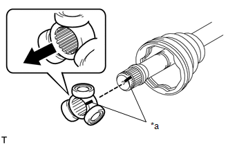
| *a | Matchmark |
| | Inboard Joint Side |
(c) Align the matchmarks and place the beveled side of the tripod joint axial spline toward the front drive outboard joint shaft assembly LH.
NOTICE:
Face the cut edge of the spline toward the inboard joint side and insert the spline onto the front drive outboard joint shaft assembly LH.
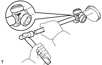
| (d) Using a brass bar and hammer, tap the tripod joint onto the front drive outboard joint shaft assembly LH. NOTICE:
|
|
| (e) Using a snap ring expander, install a new shaft snap ring. NOTICE: The shaft snap ring should be installed completely. |
|
(f) Pack the front drive inboard joint assembly LH and front axle inboard joint boot with grease from the boot kit.
Standard Grease Capacity:
140.0 to 160.0 g (4.94 to 5.64 oz)
| (g) Align the matchmarks and install the front drive inboard joint assembly LH to the front drive outboard joint shaft assembly LH. |
|
12. INSTALL FRONT DRIVE INBOARD JOINT ASSEMBLY RH
HINT:
Use the same procedure described for the LH side.
13. INSTALL FRONT AXLE INBOARD JOINT BOOT
HINT:
Use the same procedure for the RH and LH sides.
(a) Install the front axle inboard joint boot to the front drive inboard joint assembly.
NOTICE:
- Do not apply grease to the part of the front axle inboard joint boot that contacts the groove.
- Do not allow foreign matter to enter the front axle inboard joint boot.
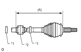
| (b) Check that the front axle inboard joint boot and front axle outboard joint boot are not stretched or contracted when the front drive shaft assembly is at the standard length. Length (A):
NOTICE: Keep the front drive shaft assembly level during inspection. If the front axle inboard joint boot and front axle outboard joint boot are stretched or contracted, correct them. |
|
.png)
14. INSTALL FRONT AXLE INBOARD JOINT BOOT CLAMP LH
(a) Install SST to the front axle inboard joint boot clamp LH, and then while pressing the front axle inboard joint boot, slightly tighten the SST bolt.
SST: 09521-24010
NOTICE:
- Correctly set the front axle inboard joint boot clamp LH to the guide groove.
- Do not damage the front axle inboard joint boot.
| (b) Tighten SST so that the front axle inboard joint boot clamp LH is pinched. Standard Clearance: 0.5 to 1.5 mm (0.0197 to 0.0590 in.) NOTICE:
|
|
(c) Remove SST from the front axle inboard joint boot clamp LH.
| (d) Using SST, measure the clearance of the front axle inboard joint boot clamp LH. SST: 09240-00020 Standard Clearance: 0.5 to 1.5 mm (0.0197 to 0.0590 in.) NOTICE:
|
|
15. INSTALL FRONT AXLE INBOARD JOINT BOOT CLAMP RH
HINT:
Use the same procedure described for the LH side.
16. INSTALL FRONT NO. 2 AXLE INBOARD JOINT BOOT CLAMP LH
| (a) Install the front No. 2 axle inboard joint boot clamp LH to the drive shaft inboard joint boot. NOTICE: Correctly set the front No. 2 axle inboard joint boot clamp LH to the guide groove. |
|
.png)
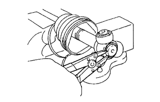
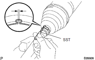
(b) Using needle-nose pliers, hold the front No. 2 axle inboard joint boot clamp LH at the claw engagement.
NOTICE:
- Do not damage the front axle inboard joint boot.
- Do not deform the claw engagement of the front No. 2 axle inboard joint boot clamp LH.
17. INSTALL FRONT NO. 2 AXLE INBOARD JOINT BOOT CLAMP RH
HINT:
Use the same procedure described for the LH side.
18. INSPECT FRONT DRIVE SHAFT
Click here .gif)
READ NEXT:
 Installation
INSTALLATION PROCEDURE 1. INSTALL FRONT DRIVE SHAFT HOLE SNAP RING LH (a) Install a new front drive shaft hole snap ring LH. NOTICE:
Do not damage the spline of the front drive inboard joint assemb
Components
COMPONENTS ILLUSTRATION *1 TAIL EXHAUST PIPE ASSEMBLY *2 EXHAUST PIPE SUPPORT *3 COMPRESSION SPRING - - N*m (kgf*cm, ft.*lbf): Specified torque - - ILLUSTRATION *
SEE MORE:
On-vehicle Inspection
ON-VEHICLE INSPECTION PROCEDURE 1. INSPECT WINDSHIELD WIPER MOTOR ASSEMBLY (a) for LH Side: (1) Check the stop (park) position. *1 Ceramic Dot *2 Louver Lip Edge *a 34 mm (1.3386 in.) *b 7.5 mm (0.2953 in.) (2) Operate the windshield wiper motor assembly.
Stop Light Relay Malfunction (C1380)
DESCRIPTION Upon receiving the hill-start assist control, dynamic radar cruise control, brake hold control or trailer sway control operating signal from the skid control ECU (brake booster with master cylinder assembly), the relay contact turns on and the stop lights come on. DTC No. Detection
