Lexus NX: Disassembly
Lexus NX Service Manual / Drivetrain / P314 (hybrid Transmission / Transaxle) / Shift Lever / Disassembly
DISASSEMBLY
PROCEDURE
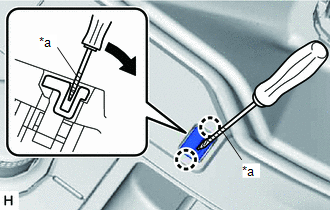
1. REMOVE SHIFT LEVER CAP
| (a) Using a screwdriver with its tip wrapped with protective tape, detach the 2 claws and remove the shift lever cap from the shift position indicator. |
|
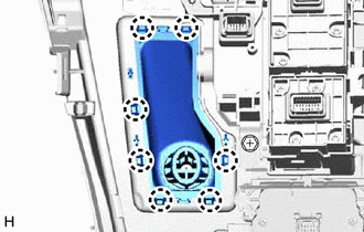
2. REMOVE SHIFTING HOLE COVER SUB-ASSEMBLY
| (a) Detach the 7 claws and remove the shifting hole cover sub-assembly from the rear upper console panel sub-assembly. |
|
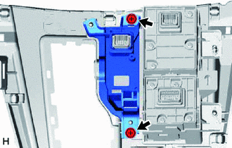
3. REMOVE SHIFT POSITION INDICATOR
| (a) Remove the 2 screws and shift position indicator from the rear upper console panel sub-assembly. |
|
READ NEXT:
 Inspection
INSPECTION PROCEDURE 1. INSPECT SHIFT LOCK CONTROL ECU (a) Measure the voltage according to the value(s) in the table below. Standard Voltage: Tester Connection Condition Specified Conditio
Reassembly
REASSEMBLY PROCEDURE 1. INSTALL SHIFT POSITION INDICATOR (a) Install the shift position indicator to the rear upper console panel sub-assembly with the 2 screws. 2. INSTALL SHIFTING HOL
Installation
INSTALLATION PROCEDURE 1. INSTALL SHIFT LEVER ASSEMBLY (a) Temporarily install the shift lever assembly with the 4 bolts. (b) Tighten the bolts in the order shown in the illustration. Torque: 12 N
SEE MORE:
Terminals Of Ecu
TERMINALS OF ECU CLOCK ASSEMBLY Terminal No. (Symbol) Wiring Color Terminal Description Condition Specified Condition I163-1 (ILL-) - Body ground G - Body ground Illumination signal ground Power switch on (ACC) Pulse generation I163-2 (E) - Body ground W-B - Body ground
Combination Meter ECU Communication Stop Mode
DESCRIPTION Detection Item Symptom Trouble Area Combination Meter ECU Communication Stop Mode Any of the following conditions are met:
Communication stop for "Combination Meter" is indicated on the "Communication Bus Check" screen of the Techstream.
Click here
Communication sys
© 2016-2026 Copyright www.lexunx.com
