Lexus NX: Installation
INSTALLATION
PROCEDURE
1. INSTALL SHIFT LEVER ASSEMBLY
(a) Temporarily install the shift lever assembly with the 4 bolts.
| (b) Tighten the bolts in the order shown in the illustration. Torque: 12 N·m {122 kgf·cm, 9 ft·lbf} |
|
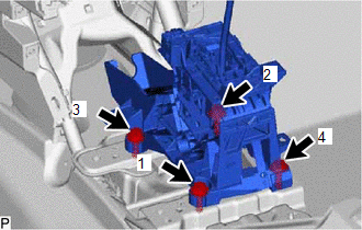
(c) Install the nut to the shift lever assembly.
(d) Connect the 2 clamps.
(e) Connect the shift lock control ECU connector.
(f) Connect the transmission control switch connector.
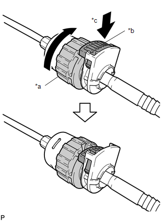
2. CONNECT TRANSMISSION CONTROL CABLE ASSEMBLY
| (a) Turn the nut of the transmission control cable 180° clockwise. While holding the nut in place, push in the stopper to lock the nut. NOTICE: Do not over-rotate the nut as it will come off the internal spring and the transmission control cable will not be reusable. HINT: If the stopper cannot be pushed in, slightly turn the nut clockwise and then push in the stopper again. |
|
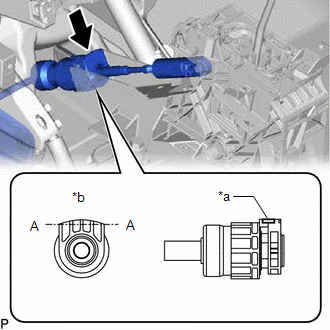
| (b) Connect the outer part of the transmission control cable assembly to the shift lever assembly. NOTICE: After installation, check that the outer part of the cable lock is protruding beyond portion A-A as shown in the illustration. |
|
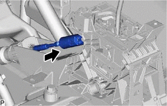
| (c) Connect the end of the transmission control cable assembly to the shift lever assembly. NOTICE:
|
|
3. INSPECT SHIFT LEVER POSITION
Click here .gif)
4. ADJUST SHIFT LEVER POSITION
Click here
5. INSTALL REAR CONSOLE BOX ASSEMBLY (w/o ASC System)
Click here
6. INSTALL NO. 1 SPEAKER WITH BOX ASSEMBLY (w/ ASC System)
Click here
READ NEXT:
 Components
COMPONENTS ILLUSTRATION *1 NO. 1 ENGINE UNDER COVER ASSEMBLY - - ILLUSTRATION *1 SHIFT LEVER POSITION SENSOR *2 TRANSMISSION CONTROL CABLE ASSEMBLY *3 CONTROL SHAFT LEVER
Removal
REMOVAL PROCEDURE 1. REMOVE NO. 1 ENGINE UNDER COVER ASSEMBLY Click here 2. DISCONNECT TRANSMISSION CONTROL CABLE ASSEMBLY (a) Remove the nut and disconnect the transmission control cable assem
SEE MORE:
Dtc Check / Clear
DTC CHECK / CLEAR CHECK FOR DTC (a) Connect the Techstream to the DLC3. (b) Turn the power switch on (IG). (c) Turn the Techstream on. (d) Enter the following menus: Body Electrical / Central Gateway / Trouble Codes. Body Electrical > Central Gateway > Trouble Codes (e) Read the DTCs. CLEAR DT
Inverter Cooling System Performance (P0A93-346)
DTC SUMMARY MALFUNCTION DESCRIPTION This DTC indicates when the temperature inside the inverter has become abnormal. The cause of this malfunction may be one of the following: Hybrid cooling system malfunction
Coolant is leaking, insufficient coolant level, frozen or the passenger of coolant is c
