Lexus NX: Inspection
INSPECTION
PROCEDURE
1. INSPECT SHIFT LOCK CONTROL ECU
| (a) Measure the voltage according to the value(s) in the table below. Standard Voltage:
HINT: Do not disconnect the shift lock control unit assembly connector. If the result is not as specified, replace the shift lock control unit assembly. |
|
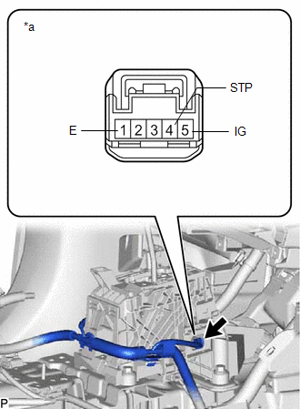
(b) Measure the resistance according to the value(s) in the table below.
Standard Resistance:
| Tester Connection | Condition | Specified Condition |
|---|---|---|
| 1 (E) - Body ground | Always | Below 1 Ω |
HINT:
Do not disconnect the shift lock control unit assembly connector.
If the result is not as specified, replace the shift lock control unit assembly.
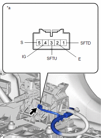
2. INSPECT TRANSMISSION CONTROL SWITCH
(a) Disconnect the shift lock solenoid connector.
| (b) Measure the resistance according to the value(s) in the table below. Standard Resistance:
If the result is not as specified, replace the shift lock control unit assembly. |
|
READ NEXT:
 Reassembly
REASSEMBLY PROCEDURE 1. INSTALL SHIFT POSITION INDICATOR (a) Install the shift position indicator to the rear upper console panel sub-assembly with the 2 screws. 2. INSTALL SHIFTING HOL
Installation
INSTALLATION PROCEDURE 1. INSTALL SHIFT LEVER ASSEMBLY (a) Temporarily install the shift lever assembly with the 4 bolts. (b) Tighten the bolts in the order shown in the illustration. Torque: 12 N
SEE MORE:
How To Proceed With Troubleshooting
CAUTION / NOTICE / HINT HINT:
Use these procedures to troubleshoot the lane tracing assist system.
*: Use the Techstream.
PROCEDURE 1. VEHICLE BROUGHT TO WORKSHOP
NEXT 2. INSPECT AUXILIARY BATTERY VOLTAGE (a) Measure the auxiliary battery voltage with the p
Heater Water Pump Circuit
DESCRIPTION The heater accessory assembly sends engine coolant to the heater core assembly while the engine is stopped to prevent heater effectiveness from becoming low. Directed by the air conditioning amplifier assembly, the hybrid vehicle control ECU operates the A/C W/PMP relay and drives the he
