Lexus NX: Reassembly
Lexus NX Service Manual / Drivetrain / P314 (hybrid Transmission / Transaxle) / Shift Lever / Reassembly
REASSEMBLY
PROCEDURE
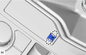
1. INSTALL SHIFT POSITION INDICATOR
| (a) Install the shift position indicator to the rear upper console panel sub-assembly with the 2 screws. |
|
.png)
2. INSTALL SHIFTING HOLE COVER SUB-ASSEMBLY
| (a) Attach the 7 claws and install the shifting hole cover sub-assembly to the rear upper console panel sub-assembly. |
|
.png)
3. INSTALL SHIFT LEVER CAP
| (a) Attach the 2 claws and install the shift lever cap to the shift position indicator. |
|
READ NEXT:
 Installation
INSTALLATION PROCEDURE 1. INSTALL SHIFT LEVER ASSEMBLY (a) Temporarily install the shift lever assembly with the 4 bolts. (b) Tighten the bolts in the order shown in the illustration. Torque: 12 N
Components
COMPONENTS ILLUSTRATION *1 NO. 1 ENGINE UNDER COVER ASSEMBLY - - ILLUSTRATION *1 SHIFT LEVER POSITION SENSOR *2 TRANSMISSION CONTROL CABLE ASSEMBLY *3 CONTROL SHAFT LEVER
SEE MORE:
Before Starting Adjustment
BEFORE STARTING ADJUSTMENT CAUTION / NOTICE / HINT NOTICE: When replacing the windshield glass of a vehicle equipped with a forward recognition camera, make sure to use a Lexus genuine part. If a non-Lexus genuine part is used, the forward recognition camera may not be able to be installed due to a
Adjustment
ADJUSTMENT CAUTION / NOTICE / HINT CAUTION: Radiofrequency radiation exposure information:
This equipment complies with FCC radiation exposure limits set forth for an uncontrolled environment.
This equipment should be kept with minimum distance of 20 cm (7.87 in.) between the radiator (antenna)
© 2016-2026 Copyright www.lexunx.com
