Lexus NX: Door Control Switch
Components
COMPONENTS
ILLUSTRATION
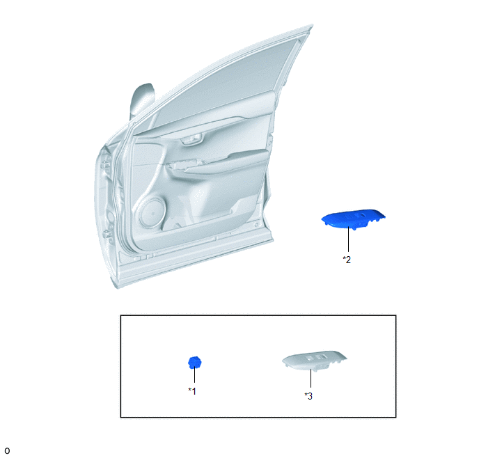
| *1 | DOOR CONTROL SWITCH ASSEMBLY | *2 | POWER WINDOW REGULATOR SWITCH ASSEMBLY WITH FRONT DOOR ARMREST BASE PANEL |
| *3 | FRONT DOOR ARMREST BASE PANEL | - | - |
Removal
REMOVAL
CAUTION / NOTICE / HINT
HINT:
- Use the same procedure for RHD and LHD vehicles.
- The procedure listed below is for LHD vehicles.
PROCEDURE
1. REMOVE POWER WINDOW REGULATOR SWITCH ASSEMBLY WITH FRONT DOOR ARMREST BASE PANEL
Click here .gif)
2. REMOVE DOOR CONTROL SWITCH ASSEMBLY
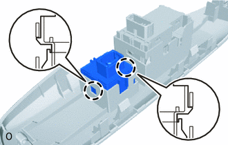
| (a) Detach the 2 claws and remove the door control switch assembly. |
|
Inspection
INSPECTION
PROCEDURE
1. INSPECT DOOR CONTROL SWITCH ASSEMBLY
| (a) Measure the resistance according to the value(s) in the table below. Standard Resistance:
If the result is not as specified, replace the door control switch assembly. |
|
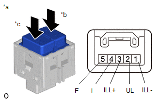
(b) Check that the LED illuminates.
(1) Apply battery voltage to the door control switch assembly and check that the LED illuminates.
OK:
| Measurement Condition | Specified Condition |
|---|---|
| Battery positive (+) → 3 (ILL+) Battery negative (-) → 1 (ILL-) | LED illuminates |
If the result is not as specified, replace the door control switch assembly.
Installation
INSTALLATION
CAUTION / NOTICE / HINT
HINT:
- Use the same procedure for RHD and LHD vehicles.
- The procedure listed below is for LHD vehicles.
PROCEDURE
1. INSTALL DOOR CONTROL SWITCH ASSEMBLY
(a) Attach the 2 claws to install the door control switch assembly.
2. INSTALL POWER WINDOW REGULATOR SWITCH ASSEMBLY WITH FRONT DOOR ARMREST BASE PANEL
Click here .gif)
READ NEXT:
 Components
COMPONENTS ILLUSTRATION *1 TRANSMITTER BATTERY *2 DOOR CONTROL TRANSMITTER HOUSING SET *3 TRANSMITTER BATTERY HOLDER *4 MECHANICAL KEY *5 ELECTRICAL TRANSMITTER SUB-ASSEMBLY
Removal
REMOVAL PROCEDURE 1. REMOVE TRANSMITTER BATTERY Click here 2. REMOVE TRANSMITTER (CARD KEY) BATTERY Click here
SEE MORE:
Front Camera Response Malfunction (C2A6D)
DESCRIPTION During self diagnosis of the parking assist ECU, the parking assist ECU sends display mode ID signals to the front television camera assembly. This DTC is stored when the output of the front television camera assembly does not match the expected output. DTC No. Detection Item DTC
Components
COMPONENTS ILLUSTRATION *1 NO. 1 AIR DUCT *2 QUICK HEATER ASSEMBLY ● Non-reusable part - -
