Lexus NX: Drive Belt
Components
COMPONENTS
ILLUSTRATION
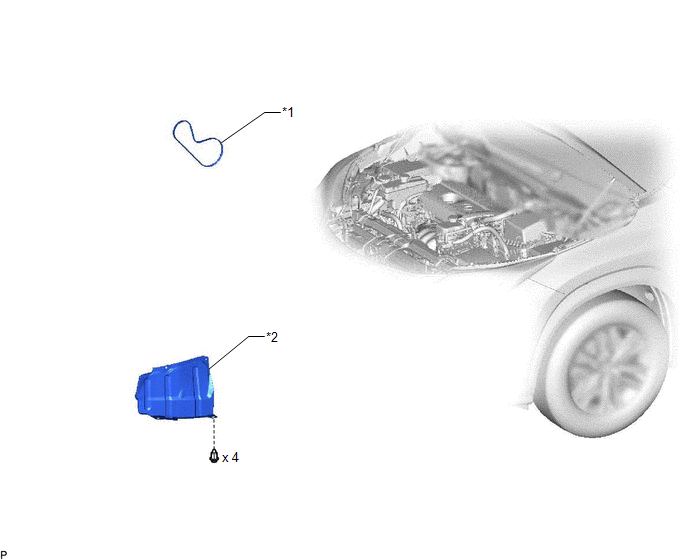
| *1 | FAN AND GENERATOR V BELT | *2 | REAR ENGINE UNDER COVER RH |
On-vehicle Inspection
ON-VEHICLE INSPECTION
PROCEDURE
1. INSPECT FAN AND GENERATOR V BELT
| (a) Check the fan and generator V belt for wear, cracks or other signs of damage. If any of the following defects is found, replace the fan and generator V belt.
|
|
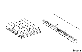
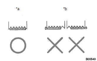
| (b) Check that the fan and generator V belt fits properly in the ribbed grooves. HINT: Check with your hand to confirm that the belt has not slipped out of the grooves on the bottom of the pulley. If it has slipped out, replace the fan and generator V belt. Install a new fan and generator V belt correctly. |
|
2. INSPECT V-RIBBED BELT TENSIONER ASSEMBLY
(a) Check that nothing gets caught in the tensioner by turning it clockwise and counterclockwise.
If a malfunction exists, replace the V-ribbed belt tensioner assembly.
Removal
REMOVAL
PROCEDURE
1. REMOVE REAR ENGINE UNDER COVER RH
Click here .gif)
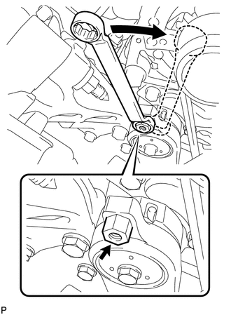
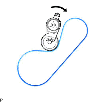
2. REMOVE FAN AND GENERATOR V BELT
| (a) Attach a wrench to the hexagonal portion of the belt tensioner as shown in the illustration, rotate the belt tensioner clockwise, and remove the fan and generator V belt. |
|
Installation
INSTALLATION
PROCEDURE
1. INSTALL FAN AND GENERATOR V BELT
HINT:
When reusing the fan and generator V belt, check the ribs and back of the fan and generator V belt for wear and cracks. If wear or a crack that reaches the core (at more than 1 point) is found, replace the fan and generator V belt.
| (a) Set the fan and generator V belt onto each part as shown in the illustration, except the water pump pulley. |
|
(b) Loosen the fan and generator V belt by turning the belt tensioner clockwise.
(c) Set the fan and generator V belt onto the water pump pulley.
NOTICE:
Make sure that the belt is attached to each pulley. In particular, make sure that the belt is securely fitted into the grooves of the crankshaft pulley.
2. INSTALL REAR ENGINE UNDER COVER RH
Click here .gif)
READ NEXT:
 On-vehicle Inspection
ON-VEHICLE INSPECTION PROCEDURE 1. INSPECT ENGINE COOLANT Click here 2. INSPECT ENGINE OIL Click here 3. INSPECT AUXILIARY BATTERY Click here 4. INSPECT AIR CLEANER FILTER ELEMENT SUB-ASSEMBLY (
SEE MORE:
Side Satellite Sensor Bus Lost Communication (RH) (B1642,B1643,B1647,B1648)
DESCRIPTION The circuit for the side collision sensor LH or RH is composed of the airbag ECU assembly, side airbag sensor assembly LH or RH and door side airbag sensor LH or RH. The door side airbag sensor LH or RH and side airbag sensor assembly LH or RH detect impacts to the vehicle and send signa
Reassembly
REASSEMBLY CAUTION / NOTICE / HINT NOTICE: Do not try to remove the black nylon tube as it is welded to the fuel suction tube assembly. Click here HINT: Perform "Inspection After Repairs" after replacing the fuel pump. Click here PROCEDURE 1. INSTALL FUEL PUMP ASSEMBLY WITH FILTER HINT: Perform
