Lexus NX: Oil Pressure Switch
Components
COMPONENTS
ILLUSTRATION
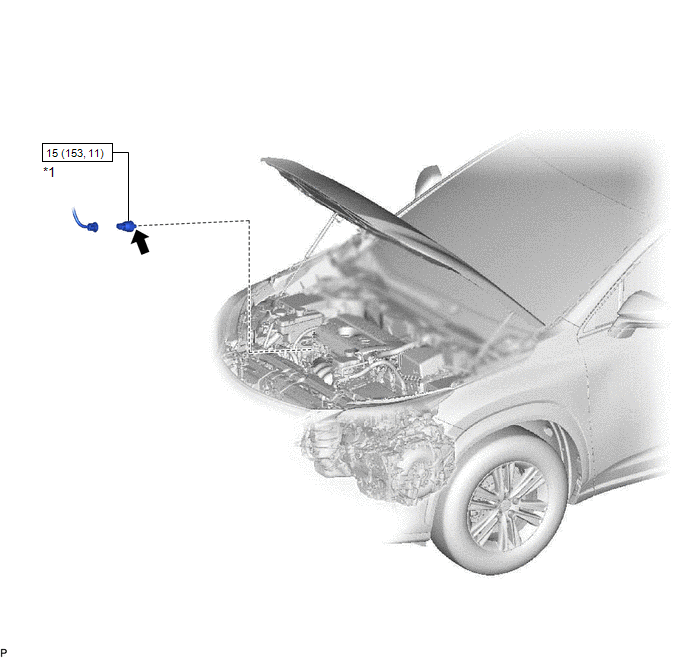
| *1 | ENGINE OIL PRESSURE SWITCH ASSEMBLY | - | - |
.png) | N*m (kgf*cm, ft.*lbf): Specified torque | .png) | TOYOTA Genuine Adhesive 1344, Three Bond 1344 or equivalent. |
| ★ | Precoated part | - | - |
Removal
REMOVAL
PROCEDURE
1. REMOVE ENGINE OIL PRESSURE SWITCH ASSEMBLY
| (a) Disconnect the engine oil pressure switch assembly connector. |
|
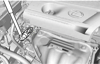
(b) Using a 24 mm deep socket wrench, remove the engine oil pressure switch assembly.
Inspection
INSPECTION
PROCEDURE
1. INSPECT ENGINE OIL PRESSURE SWITCH ASSEMBLY
(a) Disconnect the engine oil pressure switch assembly connector.
(b) Put the engine in inspection mode (maintenance mode).
Click here .gif)
(c) Start the engine.
(d) Measure the resistance according to the value(s) in the table below.
Standard Resistance:
| Tester Connection | Condition | Specified Condition |
|---|---|---|
| 1 - Body ground | Engine stopped | Below 1 Ω |
| Engine idling | 10 kΩ or higher |
If the result is not as specified, replace the engine oil pressure switch assembly.
(e) Connect the engine oil pressure switch assembly connector.
Installation
INSTALLATION
PROCEDURE
1. INSTALL ENGINE OIL PRESSURE SWITCH ASSEMBLY
(a) Remove any oil from the threads of the engine oil pressure switch assembly.
(b) Apply adhesive to 2 or 3 threads of the engine oil pressure switch assembly.
Adhesive:
TOYOTA Genuine Adhesive 1344, Three Bond 1344 or equivalent.
NOTICE:
Do not let adhesive adhere to the oil hole.
(c) Using a 24 mm deep socket wrench, install the engine oil pressure switch assembly.
Torque:
15 N·m {153 kgf·cm, 11 ft·lbf}
NOTICE:
Do not start the engine within 1 hour of installation.
(d) Connect the engine oil pressure switch assembly connector.
2. INSPECT ENGINE OIL LEVEL
Click here .gif)
3. INSPECT FOR OIL LEAK
Click here
READ NEXT:
 Components
COMPONENTS ILLUSTRATION *1 CRANKSHAFT POSITION SENSOR *2 CYLINDER HEAD COVER SUB-ASSEMBLY *3 ENGINE MOUNTING BRACKET RH *4 IGNITION COIL ASSEMBLY *5 CYLINDER HEAD COVER GASKE
Removal
REMOVAL CAUTION / NOTICE / HINT NOTICE: Do not remove the oil pump and oil pump relief valve from the timing chain cover assembly. PROCEDURE 1. REMOVE ENGINE AND TRANSAXLE Click here 2. REMOVE ENG
SEE MORE:
Front Sensor Communication Malfunction (C1AEC)
DESCRIPTION This DTC is stored when there is an open or short circuit in the communication line between the front sensors and the ECU, or when there is a malfunction in a front sensor. DTC No. Detection Item DTC Detection Condition Trouble Area C1AEC Front Sensor Communication Malfunc
Precaution
PRECAUTION PRECAUTION FOR DISCONNECTING CABLE FROM NEGATIVE AUXILIARY BATTERY TERMINAL NOTICE: After the power switch is turned off, the radio receiver assembly records various types of memory and settings. As a result, after turning the power switch off, be sure to wait for the time specified in th
