.gif)
.png)
- Power switch off
- All doors closed
- Electrical key transmitter sub-assembly not inside vehicle
-
All doors locked through wireless operation
(electrical key transmitter sub-assembly brought outside detection area*)
Lexus NX: Driver Side Door Entry Lock and Unlock Functions do not Operate
Lexus NX Service Manual / Vehicle Interior / Theft Deterrent / Keyless Entry / Smart Access System With Push-button Start (for Entry Function) / Driver Side Door Entry Lock and Unlock Functions do not Operate
DESCRIPTION
If the entry lock and unlock functions do not operate for the driver door only, the request code may not be being transmitted from the driver door or the front door outside handle assembly (for driver door) (touch sensor) may be malfunctioning. If the entry functions for other doors operate properly, communication between the electrical key transmitter sub-assembly and door control receiver is normal. In this case, there may be a problem with request code transmission (communication between the certification ECU (smart key ECU assembly) and front door outside handle assembly (for driver door) (electrical key antenna)), or there may be wave interference.
WIRING DIAGRAM
CAUTION / NOTICE / HINT
NOTICE:
-
The smart access system with push-button start (for Entry Function) uses the LIN communication system and CAN communication system. Inspect the communication function by following How to Proceed with Troubleshooting. Troubleshoot the smart access system with push-button start (for Entry Function) after confirming that the communication systems are functioning properly.
Click here
.gif)
- When using the Techstream with the power switch off, connect the Techstream to the DLC3 and turn a courtesy light switch on and off at intervals of 1.5 seconds or less until communication between the Techstream and the vehicle begins. Then select the vehicle type under manual mode and enter the following menus: Body Electrical / Smart Access. While using the Techstream, periodically turn a courtesy light switch on and off at intervals of 1.5 seconds or less to maintain communication between the Techstream and the vehicle.
- Check that there are no electrical key transmitter sub-assemblies in the vehicle.
-
Before replacing the certification ECU (smart key ECU assembly), refer to smart access system with push-button start (for Entry Function) Precaution.
Click here
- After repair, confirm that no DTCs are output by performing "DTC Output Confirmation Operation".
PROCEDURE
| 1. | CHECK POWER DOOR LOCK CONTROL SYSTEM |
(a) When the door control switch on the multiplex network master switch assembly is operated, check that the doors unlock and lock according to the switch operation.
Click here
OK:
Door locks operate normally.
| NG | .gif) | GO TO POWER DOOR LOCK CONTROL SYSTEM |
|
| 2. | CHECK FOR DTC |
(a) Check for DTCs.
Body Electrical > Smart Access > Trouble Codes| Result | Proceed to |
|---|---|
| DTCs are not output | A |
| DTCs are output | B |
| B | | GO TO DIAGNOSTIC TROUBLE CODE CHART |
|
| 3. | CHECK WAVE ENVIRONMENT |
| (a) Bring the electrical key transmitter sub-assembly approximately 0.3 m (0.984 ft.) from the front door outside handle assembly (for driver door) and perform an entry function check. Click here
|
|
| Result | Proceed to |
|---|---|
| Entry function does not operate normally | A |
| Entry function operates normally | B |
| B | | AFFECTED BY WAVE INTERFERENCE |
|
| 4. | READ VALUE USING TECHSTREAM (D-DOOR TOUCH SENSOR, D-DOOR TRIGGER SWITCH) |
(a) Connect the Techstream to the DLC3.
(b) Turn the power switch on (IG).
(c) Turn the Techstream on.
(d) Enter the following menus: Body Electrical / Smart Access / Data List.
(e) Read the Data List according to the display on the Techstream.
Body Electrical > Smart Access > Data List| Tester Display | Measurement Item | Range | Normal Condition | Diagnostic Note |
|---|---|---|---|---|
| D-Door Touch Sensor | Driver door touch sensor (unlock sensor) | ON or OFF | ON: Driver door touch sensor (unlock sensor) touched OFF: Driver door touch sensor (unlock sensor) not touched |
|
| D-Door Trigger Switch | Driver door touch sensor (lock sensor) | ON or OFF | ON: Driver door touch sensor (lock sensor) touched OFF: Driver door touch sensor (lock sensor) not touched |
|
| Tester Display |
|---|
| D-Door Touch Sensor |
| D-Door Trigger Switch |
HINT:
When checking the operation of the entry lock function several times, it can be operated up to 2 times consecutively. To operate the function 3 times or more consecutively, the doors need to be unlocked once. However, this is only for the entry lock function, other door lock operations, such as a wireless door lock operation can be performed consecutively.
OK:
The Techstream display changes correctly in response to the operation of the front door outside handle assembly (for driver door).
| NG | | GO TO STEP 6 |
|
| 5. | CHECK KEY DIAGNOSTIC MODE |
(a) Check the following antenna in key diagnostic mode.
Body Electrical > Smart Access > Utility| Tester Display |
|---|
| Communication Check(Key Diag Mode) |
(b) Select either channel 1 or channel 2 and perform key diagnostic mode inspection for each channel.
| (1) Check the electrical key antenna (for driver door): When the electrical key transmitter sub-assembly is brought within 0.7 to 1 m (2.30 to 3.28 ft.) of the front door outside handle assembly (for driver door), check that the wireless buzzer sounds. HINT:
|
|
| Result | Proceed to |
|---|---|
| Wireless buzzer does not sound | A |
| Wireless buzzer sounds | B |
| B | | REPLACE CERTIFICATION ECU (SMART KEY ECU ASSEMBLY) |
|
| 6. | CHECK HARNESS AND CONNECTOR (CERTIFICATION ECU (SMART KEY ECU ASSEMBLY) - FRONT DOOR OUTSIDE HANDLE ASSEMBLY (FOR DRIVER DOOR)) |
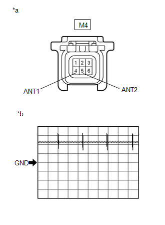
(a) Disconnect the I53 certification ECU (smart key ECU assembly) connector.
(b) Disconnect the M4 front door outside handle assembly (for driver door) connector.
(c) Measure the resistance according to the value(s) in the table below.
Standard Resistance:
| Tester Connection | Condition | Specified Condition |
|---|---|---|
| I53-4 (CLG1) - M4-4 (ANT1) | Always | Below 1 Ω |
| I53-3 (CG1B) - M4-5 (ANT2) | Always | Below 1 Ω |
| I53-4 (CLG1) or M4-4 (ANT1) - Body ground | Always | 10 kΩ or higher |
| I53-3 (CG1B) or M4-5 (ANT2) - Body ground | Always | 10 kΩ or higher |
| NG | | REPAIR OR REPLACE HARNESS OR CONNECTOR |
|
| 7. | CHECK CERTIFICATION ECU (SMART KEY ECU ASSEMBLY) (OUTPUT TO DRIVER DOOR ELECTRICAL KEY ANTENNA) |
| (a) Connect the I53 certification ECU (smart key ECU assembly) connector. |
|
(b) Measure the voltage according to the value(s) in the table below.
OK:
| Tester Connection | Condition | Tool Setting | Specified Condition |
|---|---|---|---|
| M4-4 (ANT1) - M4-5 (ANT2) | Procedure: | 5 V/DIV., 100 ms/DIV. | Pulse generation (See waveform 1) |
*: For details about the entry function detection area, refer to Operation Check.
Click here
| NG | | REPLACE CERTIFICATION ECU (SMART KEY ECU ASSEMBLY) |
|
| 8. | CHECK ENTRY LOCK OPERATION |
(a) Connect all connectors and check that the entry lock and unlock functions operate.
Click here
| Result | Proceed to |
|---|---|
| Entry function does not operate normally | A |
| Entry function operates normally | B |
| B | | END (CONNECTOR WAS NOT CONNECTED SECURELY) |
|
| 9. | REPLACE FRONT DOOR OUTSIDE HANDLE ASSEMBLY (FOR DRIVER DOOR) |
(a) Replace the front door outside handle assembly (for driver door) with a new one or the front door outside handle assembly (for front passenger door) if it is functioning properly.
Click here
|
| 10. | CHECK ENTRY LOCK OPERATION |
(a) Check that the entry lock and unlock functions operate.
Click here
| Result | Proceed to |
|---|---|
| Entry function operates normally | A |
| Entry function does not operate normally | B |
| A | | END (FRONT DOOR OUTSIDE HANDLE ASSEMBLY (FOR DRIVER DOOR) WAS DEFECTIVE) |
| B | | REPLACE CERTIFICATION ECU (SMART KEY ECU ASSEMBLY) |
READ NEXT:
 Front Passenger Side Door Entry Lock and Unlock Functions do not Operate
DESCRIPTION If the entry lock and unlock functions do not operate for the front passenger door only, the request code may not be being transmitted from the front passenger door or the front door outsi
Rear Door LH Entry Lock and Unlock Functions do not Operate
DESCRIPTION If the entry lock and unlock functions do not operate for the rear door LH only, the request code may not be being transmitted from the rear door LH or the rear door outside handle assembl
Rear Door RH Entry Lock and Unlock Functions do not Operate
DESCRIPTION If the entry lock and unlock functions do not operate for the rear door RH only, the request code may not be being transmitted from the rear door RH or the rear door outside handle assembl
SEE MORE:
Power Retractable Mirrors do not Operate with Power Retract Mirror Switch
DESCRIPTION When the outer mirror switch assembly mirror retract switch is operated, deploy/retract signals are sent to the main body ECU (multiplex network body ECU). The main body ECU (multiplex network body ECU) sends deploy/retract signals to the outer mirror control ECU assembly via CAN communi
Power Source Mode does not Change to ON (IG)
DESCRIPTION If the power switch is pressed with the electrical key transmitter sub-assembly in the cabin, the certification ECU (smart key ECU assembly) receives a signal and changes the power source mode. Related Data List and Active Test Items Problem Symptom Data List and Active Test Pow
© 2016-2026 Copyright www.lexunx.com
