Lexus NX: Inspection
Lexus NX Service Manual / Audio & Visual & Telematics / Audio / Video / Front Door Speaker / Inspection
INSPECTION
PROCEDURE
1. INSPECT FRONT NO. 1 SPEAKER ASSEMBLY
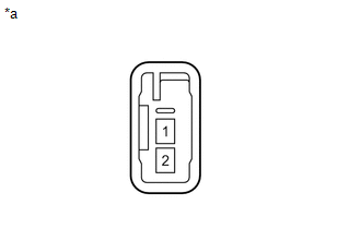
| (a) Measure the resistance according to the value(s) in the table below. Standard Resistance: for 8 Speakers
If the result is not as specified, replace the front No. 1 speaker assembly. |
|
READ NEXT:
 Installation
INSTALLATION CAUTION / NOTICE / HINT HINT:
Use the same procedure for the RH and LH sides.
The procedure listed below is for the LH side.
PROCEDURE 1. INSTALL FRONT NO. 1 SPEAKER ASSEMBLY NOTI
Components
COMPONENTS ILLUSTRATION *A for 8 Speakers *B for 10 Speakers *C for 14 Speakers - - *1 FRONT DOOR OPENING TRIM WEATHERSTRIP LH *2 FRONT NO. 2 SPEAKER ASSEMBLY *3 FR
SEE MORE:
Installation
INSTALLATION CAUTION / NOTICE / HINT HINT:
Use the same procedure for the RH and LH sides.
The procedure listed below is for the LH side.
PROCEDURE 1. INSTALL SST (a) Align the cutout on end of the shock rod of the front shock absorber assembly LH with the installation position. NOTICE: Be s
Hybrid Battery Voltage / DC/DC Converter Voltage Correlation (P1C2D-587)
DTC SUMMARY MALFUNCTION DESCRIPTION The hybrid vehicle control ECU detects a VB sensor or VL sensor malfunction. The cause of this malfunction may be one of the following: Inside of inverter voltage sensor circuit malfunction
Voltage sensor malfunction
Motor generator control ECU (MG ECU) malfu
© 2016-2026 Copyright www.lexunx.com
