Lexus NX: Driver Side Seat Position Sensor (B1653)
DESCRIPTION
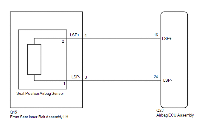
The seat position airbag sensor circuit consists of the airbag ECU assembly and seat position airbag sensor.
DTC B1653 is stored when a malfunction is detected in the seat position airbag sensor circuit.
| DTC No. | Detection Item | DTC Detection Condition | Trouble Area |
|---|---|---|---|
| B1653 | Driver Side Seat Position Sensor | One of the following conditions is met:
|
|
WIRING DIAGRAM
CAUTION / NOTICE / HINT
NOTICE:
-
After the power switch is turned off, there may be a waiting time before disconnecting the negative (-) auxiliary battery terminal.
Click here
.gif)
-
When disconnecting and reconnecting the auxiliary battery
Click here
HINT:
When disconnecting and reconnecting the auxiliary battery, there is an automatic learning function that completes learning when the respective system is used.
Click here
-
After replacing the airbag ECU assembly, refer to initialization.
Click here
PROCEDURE
| 1. | CHECK CONNECTION OF CONNECTORS |
(a) Turn the power switch off.
(b) Disconnect the cable from the negative (-) auxiliary battery terminal, and wait for at least 90 seconds.
(c) Check that the connectors are properly connected to the airbag ECU assembly and seat position airbag sensor.
| Connectors are not properly connected | .gif) | CONNECT CONNECTORS PROPERLY |
|
.gif)
| 2. | CHECK CONNECTORS |
| (a) Disconnect the connectors from the airbag ECU assembly and seat position airbag sensor. |
|
(b) Check that the connectors (on the airbag ECU assembly side and seat position airbag sensor side) are not damaged.
| Connectors are deformed or damaged | | REPLACE NO. 2 FLOOR WIRE OR FRONT SEAT INNER BELT ASSEMBLY LH |
|
| 3. | CHECK SEAT POSITION AIRBAG SENSOR CIRCUIT |
(a) Connect the cable to the negative (-) auxiliary battery terminal, and wait for at least 2 seconds.
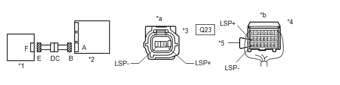
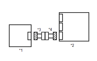
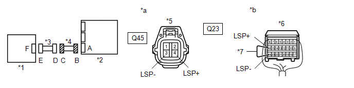
| *1 | Seat Position Airbag Sensor | *2 | Airbag ECU Assembly |
| *3 | Connector E | *4 | Connector B |
| *5 | Service Wire | - | - |
| *a | Front view of wire harness connector (to Seat Position Airbag Sensor) | *b | Rear view of wire harness connector (to Airbag ECU Assembly) |
(b) Turn the power switch on (IG).
(c) Measure the voltage according to the value(s) in the table below.
Standard Voltage:
| Tester Connection | Switch Condition | Specified Condition |
|---|---|---|
| 1 (LSP-) - Body ground | Power switch on (IG) | Below 1 V |
| 2 (LSP+) - Body ground | Power switch on (IG) | Below 1 V |
(d) Turn the power switch off.
(e) Disconnect the cable from the negative (-) auxiliary battery terminal, and wait for at least 90 seconds.
(f) Using a service wire, connect terminals 24 (LSP-) and 16 (LSP+) of connector B.
NOTICE:
Do not forcibly insert the service wire into the terminals of the connector when connecting a service wire.
(g) Measure the resistance according to the value(s) in the table below.
Standard Resistance:
| Tester Connection | Condition | Specified Condition |
|---|---|---|
| 1 (LSP-) - 2 (LSP+) | Always | Below 1 Ω |
(h) Disconnect the service wire from connector B.
(i) Measure the resistance according to the value(s) in the table below.
Standard Resistance:
| Tester Connection | Condition | Specified Condition |
|---|---|---|
| 1 (LSP-) - 2 (LSP+) | Always | 1 MΩ or higher |
| 1 (LSP-) - Body ground | Always | 1 MΩ or higher |
| 2 (LSP+) - Body ground | Always | 1 MΩ or higher |
| NG | | GO TO STEP 7 |
|
| 4. | CHECK DTC |
| (a) Connect the connectors to the airbag ECU assembly and seat position airbag sensor. |
|
(b) Connect the cable to the negative (-) auxiliary battery terminal, and wait for at least 2 seconds.
(c) Turn the power switch on (IG), and wait for at least 60 seconds.
(d) Clear the DTCs.
Click here
(e) Turn the power switch off.
(f) Turn the power switch on (IG), and wait for at least 60 seconds.
(g) Check for DTCs.
Click here
HINT:
Codes other than DTC B1653 may be output at this time, but they are not related to this check.
| DTC B1653 is not output | | USE SIMULATION METHOD TO CHECK |
|
| 5. | REPLACE SEAT POSITION AIRBAG SENSOR |
(a) Turn the power switch off.
(b) Disconnect the cable from the negative (-) auxiliary battery terminal, and wait for at least 90 seconds.
(c) Replace the seat position airbag sensor.
Click here
HINT:
Perform the inspection using parts from a normal vehicle if possible.
|
| 6. | CHECK DTC |
| (a) Connect the cable to the negative (-) auxiliary battery terminal, and wait for at least 2 seconds. |
|
(b) Turn the power switch on (IG), and wait for at least 60 seconds.
(c) Clear the DTCs.
Click here
(d) Turn the power switch off.
(e) Turn the power switch on (IG), and wait for at least 60 seconds.
(f) Check for DTCs.
Click here
HINT:
Codes other than DTC B1653 may be output at this time, but they are not related to this check.
| DTC B1653 is not output | | END (SEAT POSITION AIRBAG SENSOR WAS DEFECTIVE) |
| DTC B1653 is output | | REPLACE AIRBAG ECU ASSEMBLY |
| 7. | CHECK NO. 2 FLOOR WIRE |
(a) Disconnect the No. 2 floor wire connector from the front seat inner belt assembly LH.
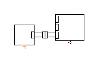
| *1 | Seat Position Airbag Sensor | *2 | Airbag ECU Assembly |
| *3 | Front Seat Inner Belt Assembly LH | *4 | No. 2 Floor Wire |
| *5 | Connector C | *6 | Connector B |
| *7 | Service Wire | - | - |
| *a | Front view of wire harness connector (to Front Seat Inner Belt Assembly LH) | *b | Rear view of wire harness connector (to Airbag ECU Assembly) |
(b) Connect the cable to the negative (-) auxiliary battery terminal, and wait for at least 2 seconds.
(c) Turn the power switch on (IG).
(d) Measure the voltage according to the value(s) in the table below.
Standard Voltage:
| Tester Connection | Switch Condition | Specified Condition |
|---|---|---|
| Q45-4 (LSP+) - Body ground | Power switch on (IG) | Below 1 V |
| Q45-3 (LSP-) - Body ground | Power switch on (IG) | Below 1 V |
(e) Turn the power switch off.
(f) Disconnect the cable from the negative (-) auxiliary battery terminal, and wait for at least 90 seconds.
(g) Using a service wire, connect terminals 24 (LSP-) and 16 (LSP+) of connector B.
NOTICE:
Do not forcibly insert the service wire into the terminals of the connector when connecting a service wire.
(h) Measure the resistance according to the value(s) in the table below.
Standard Resistance:
| Tester Connection | Condition | Specified Condition |
|---|---|---|
| Q45-4 (LSP+) - Q45-3 (LSP-) | Always | Below 1 Ω |
(i) Disconnect the service wire from connector B.
(j) Measure the resistance according to the value(s) in the table below.
Standard Resistance:
| Tester Connection | Condition | Specified Condition |
|---|---|---|
| Q45-4 (LSP+) - Q45-3 (LSP-) | Always | 1 MΩ or higher |
| Q45-4 (LSP+) - Body ground | Always | 1 MΩ or higher |
| Q45-3 (LSP-) - Body ground | Always | 1 MΩ or higher |
| OK | | REPLACE FRONT SEAT INNER BELT ASSEMBLY LH |
| NG | | REPLACE NO. 2 FLOOR WIRE |
READ NEXT:
 Seat Belt Buckle Switch (LH) (B1656)
DESCRIPTION The seat belt buckle switch LH circuit consists of the airbag ECU assembly and front seat inner belt assembly LH. DTC B1656 is stored when a malfunction is detected in the seat belt buckle
P Seat Airbag Active Mode Indicator (B1660)
DESCRIPTION The passenger airbag ON/OFF indicator circuit consists of the airbag ECU assembly and passenger airbag ON/OFF indicator. The passenger airbag ON/OFF indicator indicates the operation condi
Side Airbag Sensor RH (B1690,B1695)
DESCRIPTION The door side airbag sensor LH or RH consists of a lateral deceleration sensor, etc. If the airbag ECU assembly receives signals from the lateral deceleration sensor, it determines whether
SEE MORE:
How To Proceed With Troubleshooting
CAUTION / NOTICE / HINT HINT:
Use the following procedures to troubleshoot the clock system.
*: Use the Techstream.
PROCEDURE 1. VEHICLE BROUGHT TO WORKSHOP
NEXT 2. CUSTOMER PROBLEM ANALYSIS AND SYMPTOM CHECK
NEXT 3. INSPECT AUXILIARY
Check Mode Procedure
CHECK MODE PROCEDURE NOTICE: Enter "Signal Check" from the "DTC Check" screen displayed on the Techstream to clear the output DTCs (both present and past). HINT:
DTCs can be stored more sensitively in check mode than in normal diagnosis mode.
Perform the check mode inspection when a malfunction
