.gif)
- CH1 : Y26-3 (DS12) - Body ground
- CH2 : Y26-4 (DS22) - Body ground
Lexus NX: PBD Unit Pulse Sensor RH Circuit (B2227)
Lexus NX Service Manual / Vehicle Exterior / Door / Hatch / Power Back Door System / PBD Unit Pulse Sensor RH Circuit (B2227)
DESCRIPTION
This DTC is output when the multiplex network door ECU detects a power back door unit assembly set RH pulse malfunction.
| DTC No. | Detection Item | DTC Detection Condition | Trouble Area |
|---|---|---|---|
| B2227 | PBD Unit Pulse Sensor RH Circuit | Multiplex network door ECU detects power back door unit assembly set RH pulse malfunction |
|
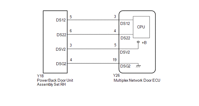
WIRING DIAGRAM
CAUTION / NOTICE / HINT
NOTICE:
If the replacement, removal and installation of the multiplex network door ECU or disconnection of the connectors of the multiplex network door ECU has been performed, initialize the power back door system.
Click here .gif)
PROCEDURE
| 1. | CHECK FOR DTC |
(a) Clear the DTCs.
Click here
(b) Check for DTCs.
Click here
OK:
DTC B2227 is not output
| OK | .gif) | USE SIMULATION METHOD TO CHECK |
|
| 2. | CHECK HARNESS AND CONNECTOR (MULTIPLEX NETWORK DOOR ECU - POWER BACK DOOR UNIT ASSEMBLY SET RH) |
(a) Disconnect the Y26 multiplex network door ECU connector.
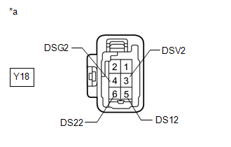
(b) Disconnect the Y18 power back door unit assembly set RH connector.
(c) Measure the resistance according to the value(s) in the table below.
Standard Resistance:
| Tester Connection | Condition | Specified Condition |
|---|---|---|
| Y26-19 (DSG2) - Y18-4 (DSG2) | Always | Below 1 Ω |
| Y26-5 (DSV2) - Y18-3 (DSV2) | Always | Below 1 Ω |
| Y26-4 (DS22) - Y18-6 (DS22) | Always | Below 1 Ω |
| Y26-3 (DS12) - Y18-5 (DS12) | Always | Below 1 Ω |
| Y26-19 (DSG2) or Y18-4 (DSG2) - Body ground | Always | 10 kΩ or higher |
| Y26-5 (DSV2) or Y18-3 (DSV2) - Body ground | Always | 10 kΩ or higher |
| Y26-4 (DS22) or Y18-6 (DS22) - Body ground | Always | 10 kΩ or higher |
| Y26-3 (DS12) or Y18-5 (DS12) - Body ground | Always | 10 kΩ or higher |
| NG | | REPAIR OR REPLACE HARNESS OR CONNECTOR |
|
| 3. | CHECK MULTIPLEX NETWORK DOOR ECU |
| (a) Disconnect the power back door unit assembly set RH connector. |
|
(b) Measure the resistance according to the value(s) in the table below.
Standard Resistance:
| Tester Connection | Condition | Specified Condition |
|---|---|---|
| Y18-4 (DSG2) - Body ground | Always | Below 1 Ω |
(c) Measure the voltage according to the value(s) in the table below.
Standard Voltage:
| Tester Connection | Condition | Specified Condition |
|---|---|---|
| Y18-5 (DS12) - Body ground | Always | 7 V or higher |
| Y18-6 (DS22) - Body ground | Always | 7 V or higher |
| Y18-3 (DSV2) - Body ground | Always | 7 V or higher |
| NG | | REPLACE MULTIPLEX NETWORK DOOR ECU |
|
| 4. | CHECK POWER BACK DOOR UNIT ASSEMBLY SET RH |
(a) Using an oscilloscope, check the waveform of each terminal from the rear of the multiplex network door ECU Y26 connector.
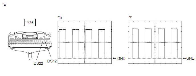
| *a | Component with harness connected (Multiplex Network Door ECU) | *b | Waveform (CH1) |
| *c | Waveform (CH2) | - | - |
Measurement Condition:
| Item | Condition |
|---|---|
| Tester Connection | |
| Tool setting | 2 V/DIV., 2 ms./DIV. |
| Vehicle condition | Open and close the back door by hand. |
HINT:
The period changes in accordance to the speed at which the back door is opened and closed by hand.
OK:
The waveform displayed is as shown in the illustration.
| OK | | REPLACE MULTIPLEX NETWORK DOOR ECU |
| NG | | REPLACE POWER BACK DOOR UNIT ASSEMBLY SET RH |
READ NEXT:
 PBD Touch Sensor LH Circuit (B222A)
DESCRIPTION This DTC is output when the multiplex network door ECU detects a power back door sensor assembly LH touch sensor malfunction. DTC No. Detection Item DTC Detection Condition Troubl
PBD Touch Sensor RH Circuit (B222B)
DESCRIPTION This DTC is output when the multiplex network door ECU detects a power back door sensor assembly RH touch sensor malfunction. DTC No. Detection Item DTC Detection Condition Troubl
Lost Communication With TCM (U0101,U0122,U0142,U0155,U0327,U1114,U1117)
DESCRIPTION These DTCs are stored when a malfunction occurs in the CAN communication circuit. DTC No. Detection Item Trouble Area U0101 Lost Communication With TCM
CAN communication
SEE MORE:
Automatic air conditioning system
Air outlets and fan speed are automatically adjusted according to the
temperature
setting.
Press the "MENU" button on the Remote Touch, then select
to display the
air conditioning control screen.
The air conditioning system can be displayed and operated on the side display.
Air conditi
Parts Location
PARTS LOCATION ILLUSTRATION *1 FORWARD RECOGNITION CAMERA *2 BRAKE BOOSTER WITH MASTER CYLINDER ASSEMBLY - SKID CONTROL ECU *3 MILLIMETER WAVE RADAR SENSOR ASSEMBLY - - ILLUSTRATION for Power Tilt and Power Telescopic *1 STEERING PAD SWITCH ASSEMBLY - LTA/LDA MAIN SWITCH
© 2016-2026 Copyright www.lexunx.com
