Lexus NX: P Seat Airbag Active Mode Indicator (B1660)
DESCRIPTION
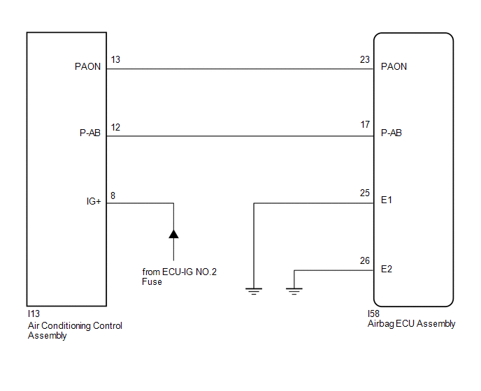
The passenger airbag ON/OFF indicator circuit consists of the airbag ECU assembly and passenger airbag ON/OFF indicator.
The passenger airbag ON/OFF indicator indicates the operation condition of the instrument panel passenger airbag assembly and front seat airbag assembly RH and LH.
DTC B1660 is stored when a malfunction is detected in the passenger airbag ON/OFF indicator circuit.
| DTC No. | Detection Item | DTC Detection Condition | Trouble Area |
|---|---|---|---|
| B1660 | P Seat Airbag Active Mode Indicator | One of the following conditions is met:
|
|
WIRING DIAGRAM
CAUTION / NOTICE / HINT
NOTICE:
-
After the power switch is turned off, there may be a waiting time before disconnecting the negative (-) auxiliary battery terminal.
Click here
.gif)
-
When disconnecting and reconnecting the auxiliary battery
Click here
HINT:
When disconnecting and reconnecting the auxiliary battery, there is an automatic learning function that completes learning when the respective system is used.
Click here
-
After replacing the airbag ECU assembly, refer to initialization.
Click here
PROCEDURE
| 1. | CHECK PASSENGER AIRBAG ON/OFF INDICATOR CONDITION |
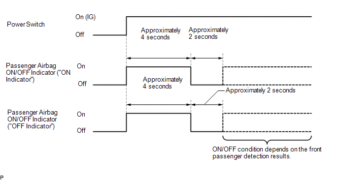
(a) Turn the power switch on (IG).
(b) Check the passenger airbag ON/OFF indicator operation.
HINT:
Refer to the normal condition of the passenger airbag ON/OFF indicator.
Click here
| ON/OFF Indicator Illumination | Proceed to |
|---|---|
| One or both indicators are always on | A |
| Both indicators are always off | B |
| B | .gif) | GO TO STEP 7 |
|
.gif)
| 2. | CHECK CONNECTION OF CONNECTORS |
(a) Turn the power switch off.
(b) Disconnect the cable from the negative (-) auxiliary battery terminal, and wait for at least 90 seconds.
(c) Check that the connectors are properly connected to the airbag ECU assembly and air conditioning control assembly.
| The connectors are not properly connected | | CONNECT CONNECTORS PROPERLY |
|
| 3. | CHECK CONNECTORS |
(a) Disconnect the connectors from the airbag ECU assembly and air conditioning control assembly.
| (b) Check that the connectors (on the airbag ECU assembly side and air conditioning control assembly side) are not damaged. |
|

| The connectors are deformed or damaged | | REPLACE HARNESS AND CONNECTOR |
|
| 4. | CHECK PASSENGER AIRBAG ON/OFF INDICATOR |
| (a) Connect the connector to the air conditioning control assembly. |
|
.png)
(b) Connect the cable to the negative (-) auxiliary battery terminal, and wait for at least 2 seconds.
(c) Turn the power switch on (IG).
(d) Check the passenger airbag ON/OFF indicator operation.
| The passenger airbag ON/OFF indicator comes on | | GO TO STEP 6 |
|
| 5. | CHECK DTC |
| (a) Connect the connectors to the airbag ECU assembly. |
|
(b) Connect the cable to the negative (-) auxiliary battery terminal, and wait for at least 2 seconds.
(c) Turn the power switch on (IG), and wait for at least 60 seconds.
(d) Clear the DTCs.
Click here
(e) Turn the power switch off.
(f) Turn the power switch on (IG), and wait for at least 60 seconds.
(g) Check for DTCs.
Click here
HINT:
Codes other than DTC B1660 may be output at this time, but they are not related to this check.
| DTC B1660 is not output | | USE SIMULATION METHOD TO CHECK |
| DTC B1660 is output | | REPLACE AIRBAG ECU ASSEMBLY |
| 6. | CHECK PASSENGER AIRBAG ON/OFF INDICATOR CIRCUIT |
(a) Disconnect the connector from the air conditioning control assembly.
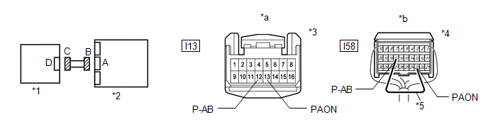
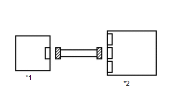
| *1 | Air Conditioning Control Assembly | *2 | Airbag ECU Assembly |
| *3 | Connector C | *4 | Connector B |
| *5 | Service Wire | - | - |
| *a | Front view of wire harness connector (to Air Conditioning Control Assembly) | *b | Rear view of wire harness connector (to Airbag ECU Assembly) |
(b) Connect the cable to the negative (-) auxiliary battery terminal, and wait for at least 2 seconds.
(c) Turn the power switch on (IG).
(d) Measure the voltage according to the value(s) in the table below.
Standard Voltage:
| Tester Connection | Switch Condition | Specified Condition |
|---|---|---|
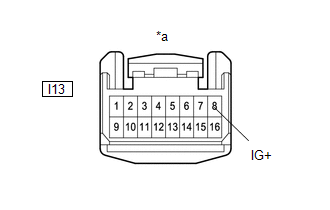
| I13-12 (P-AB) - Body ground | Power switch on (IG) | Below 1 V |
| I13-13 (PAON) - Body ground | Power switch on (IG) | Below 1 V |
(e) Turn the power switch off.
(f) Disconnect the cable from the negative (-) auxiliary battery terminal, and wait for at least 90 seconds.
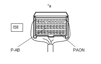
(g) Using a service wire, connect terminals 23 (PAON) and 17 (P-AB) of connector B.
NOTICE:
Do not forcibly insert the service wire into the terminals of the connector when connecting a service wire.
(h) Measure the resistance according to the value(s) in the table below.
Standard Resistance:
| Tester Connection | Condition | Specified Condition |
|---|---|---|
| I13-12 (P-AB) - I13-13 (PAON) | Always | Below 1 Ω |
(i) Disconnect the service wire from connector B.
(j) Measure the resistance according to the value(s) in the table below.
Standard Resistance:
| Tester Connection | Condition | Specified Condition |
|---|---|---|
| I13-12 (P-AB) - I13-13 (PAON) | Always | 1 MΩ or higher |
| I13-12 (P-AB) - Body ground | Always | 1 MΩ or higher |
| I13-13 (PAON) - Body ground | Always | 1 MΩ or higher |
| OK | | REPLACE AIR CONDITIONING CONTROL ASSEMBLY |
| NG | | REPLACE HARNESS AND CONNECTOR |
| 7. | CHECK CONNECTION OF CONNECTORS |
(a) Turn the power switch off.
(b) Disconnect the cable from the negative (-) auxiliary battery terminal, and wait for at least 90 seconds.
(c) Check that the connectors are properly connected to the airbag ECU assembly and air conditioning control assembly.
| The connectors are not properly connected | | CONNECT CONNECTORS PROPERLY |
|
| 8. | CHECK CONNECTORS |
(a) Disconnect the connectors from the airbag ECU assembly and air conditioning control assembly.
| (b) Check that the connectors (on the airbag ECU assembly side and air conditioning control assembly side) are not damaged. |
|
| The connectors are deformed or damaged | | REPLACE HARNESS AND CONNECTOR |
|
| 9. | CHECK PASSENGER AIRBAG ON/OFF INDICATOR CIRCUIT |
(a) Connect the cable to the negative (-) auxiliary battery terminal, and wait for at least 2 seconds.
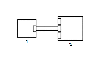
| *1 | Air Conditioning Control Assembly | *2 | Airbag ECU Assembly |
| *3 | Connector C | *4 | Connector B |
| *5 | Service Wire | - | - |
| *a | Front view of wire harness connector (to Air Conditioning Control Assembly) | *b | Rear view of wire harness connector (to Airbag ECU Assembly) |
(b) Turn the power switch on (IG).
(c) Measure the voltage according to the value(s) in the table below.
Standard Voltage:
| Tester Connection | Switch Condition | Specified Condition |
|---|---|---|
| I13-12 (P-AB) - Body ground | Power switch on (IG) | Below 1 V |
| I13-13 (PAON) - Body ground | Power switch on (IG) | Below 1 V |
(d) Turn the power switch off.
(e) Disconnect the cable from the negative (-) auxiliary battery terminal, and wait for at least 90 seconds.
(f) Using a service wire, connect terminals 23 (PAON) and 17 (P-AB) of connector B.
NOTICE:
Do not forcibly insert the service wire into the terminals of the connector when connecting a service wire.
(g) Measure the resistance according to the value(s) in the table below.
Standard Resistance:
| Tester Connection | Condition | Specified Condition |
|---|---|---|
| I13-12 (P-AB) - I13-13 (PAON) | Always | Below 1 Ω |
(h) Disconnect the service wire from connector B.
(i) Measure the resistance according to the value(s) in the table below.
Standard Resistance:
| Tester Connection | Condition | Specified Condition |
|---|---|---|
| I13-12 (P-AB) - I13-13 (PAON) | Always | 1 MΩ or higher |
| I13-12 (P-AB) - Body ground | Always | 1 MΩ or higher |
| I13-13 (PAON) - Body ground | Always | 1 MΩ or higher |
| NG | | REPLACE HARNESS AND CONNECTOR |
|
| 10. | CHECK PASSENGER AIRBAG ON/OFF INDICATOR (SOURCE VOLTAGE) |
| (a) Connect the connectors to the airbag ECU assembly. |
|
(b) Connect the cable to the negative (-) auxiliary battery terminal, and wait for at least 2 seconds.
(c) Turn the power switch on (IG).
(d) Measure the voltage according to the value(s) in the table below.
Standard Voltage:
| Tester Connection | Switch Condition | Specified Condition |
|---|---|---|
| I13-8 (IG+) - Body ground | Power switch on (IG) | 11 to 14 V |
| NG | | REPAIR OR REPLACE HARNESS OR CONNECTOR |
|
| 11. | CHECK PASSENGER AIRBAG ON/OFF INDICATOR |
| (a) Turn the power switch off. |
|
(b) Disconnect the cable from the negative (-) auxiliary battery terminal, and wait for at least 90 seconds.
(c) Connect the connector to the air conditioning control assembly.
(d) Disconnect the connectors from the airbag ECU assembly.
(e) Using a service wire, connect terminal 23 (PAON) and body ground.
(f) Using a service wire, connect terminal 17 (P-AB) and body ground.
(g) Connect the cable to the negative (-) auxiliary battery terminal, and wait for at least 2 seconds.
(h) Turn the power switch on (IG).
(i) Check the indicator according to the table below.
OK:
| Tester Connection | Switch Condition | Passenger Airbag ON/OFF Indicator |
|---|---|---|
| I58-23 (PAON) - Body ground | Power switch on (IG) | "ON" comes on |
| I58-17 (P-AB) - Body ground | Power switch on (IG) | "OFF" comes on |
(j) Disconnect the service wire from airbag ECU assembly.
| NG | | REPLACE AIR CONDITIONING CONTROL ASSEMBLY |
|
| 12. | CHECK DTC |
| (a) Turn the power switch off. |
|
(b) Disconnect the cable from the negative (-) auxiliary battery terminal, and wait for at least 90 seconds.
(c) Connect the connectors to the airbag ECU assembly.
(d) Connect the cable to the negative (-) auxiliary battery terminal and wait for at least 2 seconds.
(e) Turn the power switch on (IG), and wait for at least 60 seconds.
(f) Clear the DTCs.
Click here
(g) Turn the power switch off.
(h) Turn the power switch on (IG), and wait for at least 60 seconds.
(i) Check for DTCs.
Click here
HINT:
Codes other than DTC B1660 may be output at this time, but they are not related to this check.
| DTC B1660 is not output | | USE SIMULATION METHOD TO CHECK |
| DTC B1660 is output | | REPLACE AIRBAG ECU ASSEMBLY |
READ NEXT:
 Side Airbag Sensor RH (B1690,B1695)
DESCRIPTION The door side airbag sensor LH or RH consists of a lateral deceleration sensor, etc. If the airbag ECU assembly receives signals from the lateral deceleration sensor, it determines whether
Lost Communication with Side Airbag Sensor RH (B1692,B1693,B1697,B1698)
DESCRIPTION The circuit for the side collision sensor LH or RH is composed of the airbag ECU assembly, side airbag sensor assembly LH or RH and door side airbag sensor LH or RH. The side airbag sensor
Short in D Squib Circuit (B1800-B1803)
DESCRIPTION The driver side squib circuit consists of the airbag ECU assembly, spiral cable sub-assembly and horn button assembly. The circuit instructs the SRS to deploy when deployment conditions ar
SEE MORE:
Cursor or Map Rotates when Vehicle Stopped
PROCEDURE 1. CHECK CONDITION (a) Check with the customer if the vehicle has been turned by a turntable. OK: Vehicle has not been turned by a turntable. HINT: If the vehicle is turned on a turntable with the power switch on (IG), the system may store the angular velocity. As a result, th
Luggage Compartment Room Light
ComponentsCOMPONENTS ILLUSTRATION *1 NO. 1 LUGGAGE COMPARTMENT LIGHT ASSEMBLY - - RemovalREMOVAL PROCEDURE 1. REMOVE NO. 1 LUGGAGE COMPARTMENT LIGHT ASSEMBLY (for LH Side) (a) Put protective tape around the No. 1 luggage compartment light assembly. Protective Tape (b) Using
