Lexus NX: Evaporator Temperature Circuit or Evaporator Fin Thermistor (B1413)
DESCRIPTION
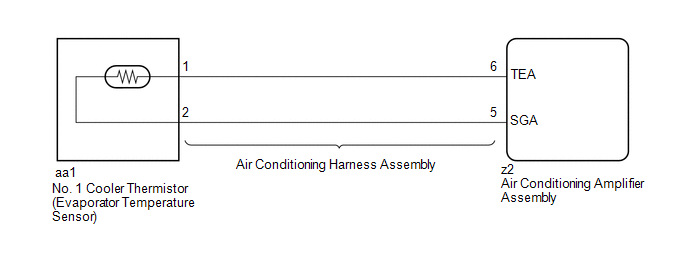
The No. 1 cooler thermistor (evaporator temperature sensor) is installed on the evaporator in the air conditioner unit to detect the temperature of the air that has passed through the evaporator and is used to control the air conditioning. It sends signals to the air conditioning amplifier assembly. The resistance of the No. 1 cooler thermistor (evaporator temperature sensor) changes in accordance with the cooled air temperature that has passed through the evaporator. As the temperature decreases, the resistance increases. As the temperature increases, the resistance decreases.
The air conditioning amplifier assembly applies voltage (5 V) to the No. 1 cooler thermistor (evaporator temperature sensor) and reads voltage changes as the resistance of the No. 1 cooler thermistor (evaporator temperature sensor) changes. This sensor is used for frost prevention.
| DTC No. | Detection Item | DTC Detection Condition | Trouble Area | Memory | Note |
|---|---|---|---|---|---|
| B1413 | Evaporator Temperature Circuit or Evaporator Fin Thermistor | Open or short in No. 1 cooler thermistor (evaporator temperature sensor) circuit |
| Memorized (4 seconds or more) | - |
HINT:
The air conditioning amplifier assembly stores the DTC of the respective malfunction if it has occurred for the period of time indicated in the brackets.
WIRING DIAGRAM
CAUTION / NOTICE / HINT
NOTICE:
When the auxiliary battery is disconnected or the air conditioning amplifier assembly is replaced, be sure to perform servo motor initialization.
Click here .gif)
PROCEDURE
| 1. | READ VALUE USING TECHSTREAM |
(a) Connect the Techstream to the DLC3.
(b) Turn the power switch on (IG).
(c) Turn the Techstream on.
(d) Enter the following menus: Body Electrical / Air Conditioner / Data List.
(e) Check the value(s) by referring to the table below.
Body Electrical > Air Conditioner > Data List| Tester Display | Measurement Item | Range | Normal Condition | Diagnostic Note |
|---|---|---|---|---|
| Evaporator Fin Thermistor | No. 1 cooler thermistor (evaporator temperature sensor) | Min.: -29.70°C (-21.46°F) Max.: 59.55°C (139.19°F) | Actual evaporator temperature displayed | - |
| Tester Display |
|---|
| Evaporator Fin Thermistor |
OK:
The display is as specified in the normal condition column.
| Result | Proceed to |
|---|---|
| OK (When troubleshooting according to Problem Symptoms Table) | A |
| OK (When troubleshooting according to the DTC) | B |
| NG | C |
| A | .gif) | PROCEED TO NEXT SUSPECTED AREA SHOWN IN PROBLEM SYMPTOMS TABLE |
| B | | REPLACE AIR CONDITIONING AMPLIFIER ASSEMBLY |
|
.gif)
| 2. | INSPECT NO. 1 COOLER THERMISTOR (EVAPORATOR TEMPERATURE SENSOR) |
(a) Remove the No. 1 cooler thermistor (evaporator temperature sensor).
Click here
(b) Inspect the No. 1 cooler thermistor (evaporator temperature sensor).
Click here
| NG | | REPLACE NO. 1 COOLER THERMISTOR (EVAPORATOR TEMPERATURE SENSOR) |
|
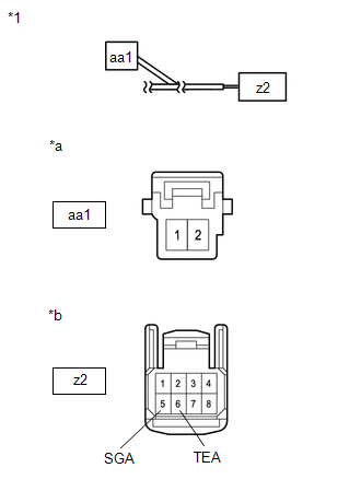
| 3. | CHECK AIR CONDITIONING HARNESS ASSEMBLY |
| (a) Disconnect the air conditioning harness assembly connector. |
|
(b) Measure the resistance according to the value(s) in the table below.
Standard Resistance:
| Tester Connection | Condition | Specified Condition |
|---|---|---|
| z2-6 (TEA) - aa1-1 | Always | Below 1 Ω |
| z2-5 (SGA) - aa1-2 | Always | Below 1 Ω |
| z2-6 (TEA) or aa1-1 - Body ground | Always | 10 kΩ or higher |
| z2-5 (SGA) or aa1-2 - Body ground | Always | 10 kΩ or higher |
| OK | | REPLACE AIR CONDITIONING AMPLIFIER ASSEMBLY |
| NG | | REPLACE AIR CONDITIONING HARNESS ASSEMBLY |
READ NEXT:
 Open in Pressure Sensor Circuit / Abnormal Refrigerant Pressure (B1423)
DESCRIPTION This DTC is stored if refrigerant pressure on the high pressure side is extremely low (176 kPa (1.8 kgf/cm2, 26 psi) or less) or extremely high (3025 kPa (30.8 kgf/cm2, 439 psi) or more).
Air Mix Damper Control Servo Motor Circuit (Passenger Side) (B1441)
DESCRIPTION The No. 1 air conditioning radiator damper servo sub-assembly (front passenger side air mix) sends pulse signals to indicate the damper position to the air conditioning amplifier assembly.
Air Inlet Damper Control Servo Motor Circuit (B1442)
DESCRIPTION The No. 1 blower damper servo sub-assembly sends pulse signals to inform the air conditioning amplifier assembly of the damper position. The air conditioning amplifier assembly activates t
SEE MORE:
Part of HV Gate Blocking Range/Performance (P321F-319)
DESCRIPTION Refer to the description for DTC P321E-318. Click here DTC No. Detection Item DTC Detection Condition Trouble Area MIL Warning Indicate P321F-319 Part of HV Gate Blocking Range/Performance An open or ground short in the HV gate block signal circuit when the gate is
DC / DC Converter Status Circuit High Input (P0A10-263)
DESCRIPTION Refer to the description for DTC P0A08-264. Click here The hybrid vehicle control ECU sends a signal to the DC/DC converter to prohibit its control and receives signals indicating a normal or abnormal condition of the 12 V charging system via the NODD signal line. If the DC/DC convert
