Lexus NX: Air Inlet Damper Control Servo Motor Circuit (B1442)
DESCRIPTION
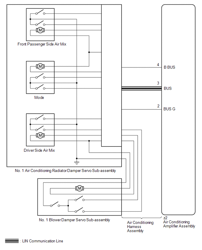
The No. 1 blower damper servo sub-assembly sends pulse signals to inform the air conditioning amplifier assembly of the damper position. The air conditioning amplifier assembly activates the motor (normal, reverse) based on the signals to move the air inlet mode selection No. 1 blower damper servo sub-assembly to any position, which controls the intake air settings (FRESH, FRESH/RECIRCULATION, and RECIRCULATION).
| DTC No. | Detection Item | DTC Detection Condition | Trouble Area | Memory | Note |
|---|---|---|---|---|---|
| B1442 | Air Inlet Damper Control Servo Motor Circuit | Air inlet damper position sensor value does not change even if air conditioning amplifier assembly operates No. 1 blower damper servo sub-assembly |
| Memorized (30 seconds or more) | - |
HINT:
The air conditioning amplifier assembly stores the DTC of the respective malfunction if it has occurred for the period of time indicated in the brackets.
WIRING DIAGRAM
CAUTION / NOTICE / HINT
NOTICE:
- When DTC B1441, B1442, B1443 and B1446 are output at same time, there would be malfunctioning on No. 1 air conditioning radiator damper servo sub-assembly.
-
When the auxiliary battery is disconnected or the air conditioning amplifier assembly is replaced, be sure to perform servo motor initialization.
Click here
.gif)
HINT:
Confirm that no mechanical problem is present because this diagnostic code can be output when either a damper link or the damper is mechanically locked.
PROCEDURE
| 1. | CHECK FOR DTC |
(a) Clear the DTC.
Click here
(b) Check for DTC.
Click here
| Result | Proceed to |
|---|---|
| DTC B1442 is not output | A |
| DTC B1442 is output | B |
| DTC B1442 and B1497 are output | C |
| A | .gif) | USE SIMULATION METHOD TO CHECK |
| C | | GO TO DTC B1497 |
|
.gif)
| 2. | READ VALUE USING TECHSTREAM |
(a) Connect the Techstream to the DLC3.
(b) Turn the power switch on (IG).
(c) Turn the Techstream on.
(d) Operate the recirculation/fresh switch.
(e) Enter the following menus: Body Electrical / Air Conditioner / Data List.
(f) Check the value(s) by referring to the table below.
Body Electrical > Air Conditioner > Data List| Tester Display | Measurement Item | Range | Normal Condition | Diagnostic Note |
|---|---|---|---|---|
| Air Inlet Damper Targ Pulse | No. 1 blower damper servo sub-assembly target pulse | Min.: 128 Max.: 383 | RECIRCULATION: 258 (pulse) FRESH: 235 (pulse) | - |
| Air Inlet Damper Actual Pulse | No. 1 blower damper servo sub-assembly actual pulse | Min.: 128 Max.: 383 | RECIRCULATION: 258 (pulse) FRESH: 235 (pulse) | - |
| Tester Display |
|---|
| Air Inlet Damper Targ Pulse |
| Air Inlet Damper Actual Pulse |
OK:
When the recirculation/fresh switch is turned to recirculation mode or fresh mode, the actual pulse changes following the target pulse.
| Result | Proceed to |
|---|---|
| Target pulse and actual pulse do not change | A |
| Target pulse changes but actual pulse does not change | B |
| Actual pulse changes following the target pulse (When troubleshooting according to the DTC) | C |
| Actual pulse changes following the target pulse (When troubleshooting according to Problem Symptoms Table) | D |
| A | | REPLACE AIR CONDITIONING AMPLIFIER ASSEMBLY |
| C | | GO TO STEP 6 |
| D | | PROCEED TO NEXT SUSPECTED AREA SHOWN IN PROBLEM SYMPTOMS TABLE |
|
| 3. | CHECK NO. 1 BLOWER DAMPER SERVO SUB-ASSEMBLY |
(a) Replace the No. 1 blower damper servo sub-assembly.
Click here
HINT:
Since the servo motor cannot be inspected while it is removed from the vehicle, replace the servo motor with a new or known good one and check that the condition returns to normal.
(b) Clear the DTC.
Click here
(c) Check for DTC.
Click here
| Result | Proceed to |
|---|---|
| DTC B1442 is not output | A |
| DTC B1442 is output | B |
| A | | END (NO. 1 BLOWER DAMPER SERVO SUB-ASSEMBLY IS DEFECTIVE) |
|
| 4. | CHECK NO. 1 AIR CONDITIONING RADIATOR DAMPER SERVO SUB-ASSEMBLY |
(a) Replace the No. 1 air conditioning radiator damper servo sub-assembly.
Click here
HINT:
Since the servo motor cannot be inspected while it is removed from the vehicle, replace the servo motor with a new or known good one and check that the condition returns to normal.
(b) Clear the DTC.
Click here
(c) Check for DTC.
Click here
| Result | Proceed to |
|---|---|
| DTC B1442 is not output | A |
| DTC B1442 is output | B |
| A | | END (NO. 1 AIR CONDITIONING RADIATOR DAMPER SERVO SUB-ASSEMBLY IS DEFECTIVE) |
|
| 5. | CHECK AIR CONDITIONING HARNESS ASSEMBLY |
(a) Replace the air conditioning harness assembly.
Click here
HINT:
Since the air conditioning harness assembly cannot be inspected while it is removed from the vehicle, replace the air conditioning harness assembly with a new or known good one and check that the condition returns to normal.
(b) Clear the DTC.
Click here
(c) Check for DTC.
Click here
| Result | Proceed to |
|---|---|
| DTC B1442 is not output | A |
| DTC B1442 is output | B |
| A | | END (AIR CONDITIONING HARNESS ASSEMBLY IS DEFECTIVE) |
| B | | REPLACE AIR CONDITIONING AMPLIFIER ASSEMBLY |
| 6. | CHECK FOR DTC |
(a) Clear the DTC.
Click here
(b) Check for DTC.
Click here
| Result | Proceed to |
|---|---|
| DTC B1442 is not output | A |
| DTC B1442 is output | B |
| A | | USE SIMULATION METHOD TO CHECK |
| B | | REPLACE AIR CONDITIONING AMPLIFIER ASSEMBLY |
READ NEXT:
 Air Outlet Damper Control Servo Motor Circuit (B1443)
DESCRIPTION The No. 1 air conditioning radiator damper servo sub-assembly (mode) sends pulse signals to inform the air conditioning amplifier assembly of the damper position. The air conditioning ampl
Air Mix Damper Control Servo Motor Circuit (Driver Side) (B1446)
DESCRIPTION The No. 1 air conditioning radiator damper servo sub-assembly (driver side air mix) sends pulse signals to inform the air conditioning amplifier assembly of the damper position. The air co
Air Outlet Damper Control Servo Motor Circuit (Rear) (B1449)
DESCRIPTION The No. 2 air conditioning radiator damper servo sub-assembly sends pulse signals to inform the air conditioning amplifier assembly of the damper position. The air conditioning amplifier a
SEE MORE:
Removal
REMOVAL PROCEDURE 1. REMOVE FUEL TANK ASSEMBLY Click here 2. DISCONNECT FUEL TANK MAIN TUBE SUB-ASSEMBLY (a) Remove the tube joint clip, then disconnect the fuel tank main tube sub-assembly from the fuel suction plate sub-assembly. NOTICE:
Remove dirt or foreign objects on the fuel tube j
Removal
REMOVAL PROCEDURE 1. REMOVE NO. 1 SPEAKER WITH BOX ASSEMBLY (w/ ASC System) Click here 2. REMOVE REAR CONSOLE BOX ASSEMBLY (w/o ASC System) Click here 3. DISCONNECT TRANSMISSION CONTROL CABLE ASSEMBLY Click here 4. REMOVE INVERTER WITH CONVERTER ASSEMBLY Click here 5. REMOVE NO. 1 ENGINE U
