- DTC judgment completed
- System normal
Lexus NX: Exhaust Gas Recirculation Control Circuit (P0403)
Lexus NX Service Manual / Engine & Hybrid System / 2ar-fxe (engine Control) / Sfi System / Exhaust Gas Recirculation Control Circuit (P0403)
DESCRIPTION
Refer to DTC P0401.
Click here .gif)
| DTC No. | Detection Item | DTC Detection Condition | Trouble Area | MIL | Memory |
|---|---|---|---|---|---|
| P0403 | Exhaust Gas Recirculation Control Circuit | Both of the following conditions are met: (1 trip detection logic)
|
| Comes on | DTC stored |
MONITOR DESCRIPTION
This DTC is stored if an open or short in the EGR valve assembly circuit is detected.
Example:
- If the EGR1, EGR2, EGR3 or EGR4 terminal output voltage is excessively low, but the step motor is still operating, the ECM determines that there is a short in the EGR valve assembly circuit, and stores this DTC.
- If the EGR1, EGR2, EGR3 or EGR4 terminal output voltage is excessively low, and the step motor is not operating, the ECM determines that there is an open in the EGR valve assembly circuit, and stores this DTC.
MONITOR STRATEGY
| Related DTCs | P0403: EGR valve circuit range check |
| Required Sensors/Components (Main) | EGR valve assembly |
| Required Sensors/Components (Related) | - |
| Frequency of Operation | Continuous |
| Duration | - |
| MIL Operation | Immediate |
| Sequence of Operation | None |
TYPICAL ENABLING CONDITIONS
| Monitor runs whenever the following DTCs are not stored | None |
| All of the following conditions are met | - |
| Engine | Running |
| Auxiliary battery voltage | 10.5 V or higher |
| Time after power switch off to on (IG) | 0.5 seconds or more |
TYPICAL MALFUNCTION THRESHOLDS
| One of the following conditions is met | Conditions A, B, C or D |
| A. All of the following conditions are met | - |
| EGR1 output terminal voltage | Low |
| Either of the following conditions is met | 1 or 2 |
| 1. Step motor | Driving |
| 2. EGR1 | Not operating |
| B. All of the following conditions are met | - |
| EGR2 output terminal voltage | Low |
| Either of the following conditions is met | 3 or 4 |
| 3. Step motor | Driving |
| 4. EGR2 | Not operating |
| C. All of the following conditions are met | - |
| EGR3 output terminal voltage | Low |
| Either of the following conditions is met | 5 or 6 |
| 5. Step motor | Driving |
| 6. EGR3 | Not operating |
| D. All of the following conditions are met | - |
| EGR4 output terminal voltage | Low |
| Either of the following conditions is met | 7 or 8 |
| 7. Step motor | Driving |
| 8. EGR4 | Not operating |
CONFIRMATION DRIVING PATTERN
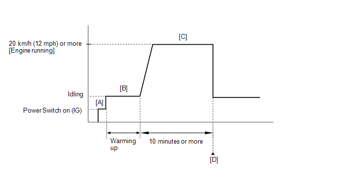
- Connect the Techstream to the DLC3.
- Turn the power switch on (IG) and turn the Techstream on.
- Clear the DTCs (even if no DTCs are stored, perform the clear DTC procedure).
- Turn the power switch off and wait for at least 30 seconds.
- Turn the power switch on (IG) and turn the Techstream on [A].
-
Put the engine in inspection mode (maintenance mode).
Click here
- Start the engine and warm it up [B].
-
With the engine running, drive the vehicle at 20 km/h (12 mph) or more for 10 minutes [C].
CAUTION:
When performing the confirmation driving pattern, obey all speed limits and traffic laws.
HINT:
If the engine stops, further depress the accelerator pedal to restart the engine.
- Enter the following menus: Powertrain / Engine and ECT / Trouble Codes [D].
-
Read the pending DTCs.
HINT:
- If a pending DTC is output, the system is malfunctioning.
- If a pending DTC is not output, perform the following procedure.
- Enter the following menus: Powertrain / Engine and ECT / Utility / All Readiness.
- Input the DTC: P0403.
-
Check the DTC judgment result.
Techstream Display
Description
NORMAL
ABNORMAL
- DTC judgment completed
- System abnormal
INCOMPLETE
- DTC judgment not completed
- Perform driving pattern after confirming DTC enabling conditions
N/A
- Unable to perform DTC judgment
- Number of DTCs which do not fulfill DTC preconditions has reached ECU memory limit
HINT:
- If the judgment result shows NORMAL, the system is normal.
- If the judgment result shows ABNORMAL, the system has a malfunction.
-
If the judgment result is INCOMPLETE or N/A and no pending DTC is output, perform a universal trip and check for permanent DTCs.
Click here
HINT:
- If a permanent DTC is output, the system is malfunctioning.
- If no permanent DTC is output, the system is normal.
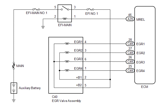
WIRING DIAGRAM
CAUTION / NOTICE / HINT
NOTICE:
Inspect the fuses for circuits related to this system before performing the following procedure.
HINT:
Read freeze frame data using the Techstream. The ECM records vehicle and driving condition information as freeze frame data the moment a DTC is stored. When troubleshooting, freeze frame data can help determine if the vehicle was moving or stationary, if the engine was warmed up or not, if the air fuel ratio was lean or rich, and other data from the time the malfunction occurred.
PROCEDURE
| 1. | PERFORM ACTIVE TEST USING TECHSTREAM (CONTROL THE EGR STEP POSITION) |
(a) Connect the Techstream to the DLC3.
(b) Turn the power switch on (IG).
(c) Turn the Techstream on.
(d) Put the engine in inspection mode (maintenance mode).
Click here
| Tester Display |
|---|
| Inspection Mode |
(e) Start the engine and warm it up until the engine coolant temperature reaches 75°C (167°F) or higher.
HINT:
The A/C switch and all accessory switches should be off.
(f) Enter the following menus: Powertrain / Engine and ECT / Active Test / Control the EGR Step Position / Primary / MAP and Throttle Idle Position.
Powertrain > Engine and ECT > Active Test| Active Test Display |
|---|
| Control the EGR Step Position |
| Data List Display |
|---|
| MAP |
| Throttle Idle Position |
(g) Confirm that the Throttle Idle Position is ON and check the MAP values in the Data List while performing the Active Test.
HINT:
- Do not leave the EGR valve open for 10 seconds or more during the Active Test.
- Be sure to return the EGR valve to step 0 when the Active Test is completed.
- Do not open the EGR valve 30 steps or more during the Active Test.
OK:
MAP change in response to EGR step position when Throttle Idle Position is ON in Data List.
Standard:
| - | EGR Step Position (Active Test) | |
|---|---|---|
| 0 Steps | 0 to 30 Steps | |
| MAP (Data List) | (EGR valve is fully closed) | MAP value is at least +10 kPa (75 mmHg) higher than when EGR valve is fully closed |
HINT:
- While performing the Active Test, if the increase in the value of MAP is small, the EGR valve assembly may be a malfunctioning.
- Even if the EGR valve assembly is malfunctioning, rough idling or an increase in the value of MAP may occur while performing the Active Test. However, the amount that the value of MAP increases will be smaller than normal.
| OK | .gif) | CHECK FOR INTERMITTENT PROBLEMS |
|
.gif)
| 2. | INSPECT EGR VALVE ASSEMBLY |
(a) Inspect the EGR valve assembly.
Click here
HINT:
Perform "Inspection After Repair" after replacing the EGR valve assembly.
Click here
| NG | | REPLACE EGR VALVE ASSEMBLY |
|
| 3. | CHECK TERMINAL VOLTAGE (POWER SOURCE OF EGR VALVE ASSEMBLY) |
| (a) Disconnect the EGR valve assembly connector. |
|
(b) Turn the power switch on (IG).
(c) Measure the voltage according to the value(s) in the table below.
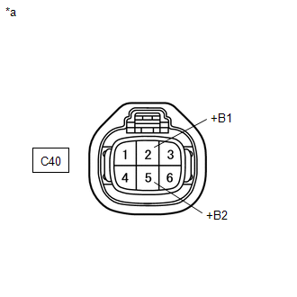
Standard Voltage:
| Tester Connection | Condition | Specified Condition |
|---|---|---|
| C40-2 (+B1) - Body ground | Power switch on (IG) | 11 to 14 V |
| C40-5 (+B2) - Body ground | Power switch on (IG) | 11 to 14 V |
| NG | | GO TO STEP 5 |
|
| 4. | CHECK HARNESS AND CONNECTOR (EGR VALVE ASSEMBLY - ECM) |
(a) Disconnect the EGR valve assembly connector.
(b) Disconnect the ECM connector.
(c) Measure the resistance according to the value(s) in the table below.
Standard Resistance:
| Tester Connection | Condition | Specified Condition |
|---|---|---|
| C40-4 (EGR1) - C48-28 (EGR1) | Always | Below 1 Ω |
| C40-3 (EGR2) - C48-27 (EGR2) | Always | Below 1 Ω |
| C40-6 (EGR3) - C48-26 (EGR3) | Always | Below 1 Ω |
| C40-1 (EGR4) - C48-25 (EGR4) | Always | Below 1 Ω |
| C40-4 (EGR1) or C48-28 (EGR1) - Body ground | Always | 10 kΩ or higher |
| C40-3 (EGR2) or C48-27 (EGR2) - Body ground | Always | 10 kΩ or higher |
| C40-6 (EGR3) or C48-26 (EGR3) - Body ground | Always | 10 kΩ or higher |
| C40-1 (EGR4) or C48-25 (EGR4) - Body ground | Always | 10 kΩ or higher |
| OK | | REPLACE ECM |
| NG | | REPAIR OR REPLACE HARNESS OR CONNECTOR |
| 5. | CHECK HARNESS AND CONNECTOR (EFI-MAIN RELAY - EGR VALVE ASSEMBLY) |
(a) Disconnect the EGR valve assembly connector.
(b) Remove the EFI-MAIN relay from the No. 1 engine room relay block and junction block assembly.
(c) Measure the resistance according to the value(s) in the table below.
Standard Resistance:
| Tester Connection | Condition | Specified Condition |
|---|---|---|
| 3 (EFI-MAIN relay) - C40-2 (+B1) | Always | Below 1 Ω |
| 3 (EFI-MAIN relay) - C40-5 (+B2) | Always | Below 1 Ω |
| 3 (EFI-MAIN relay) or C40-2 (+B1) - Body ground | Always | 10 kΩ or higher |
| 3 (EFI-MAIN relay) or C40-5 (+B2) - Body ground | Always | 10 kΩ or higher |
| OK | | GO TO ECM POWER SOURCE CIRCUIT |
| NG | | REPAIR OR REPLACE HARNESS OR CONNECTOR |
READ NEXT:
 Catalyst System Efficiency Below Threshold (Bank 1) (P0420)
MONITOR DESCRIPTION The ECM uses sensors mounted in front of and behind the Three-Way Catalytic Converter (TWC) to monitor its efficiency. The first sensor, the air fuel ratio sensor, sends pre-cataly
Evaporative Emission System Leak Detection Reference Orifice Low Flow (P043E,P043F,P2401,P2402,P2419)
DTC SUMMARY DTC No. Detection Item DTC Detection Condition Trouble Area MIL Memory P043E Evaporative Emission System Leak Detection Reference Orifice Low Flow Reference orifice cl
Evaporative Emission Control System Incorrect Purge Flow (P0441)
DTC SUMMARY DTC No. Detection Item DTC Detection Condition Trouble Area MIL Memory P0441 Evaporative Emission Control System Incorrect Purge Flow One of the following conditions m
SEE MORE:
On-vehicle Inspection
ON-VEHICLE INSPECTION CAUTION / NOTICE / HINT CAUTION: Be sure to follow the correct removal and installation procedures of the instrument panel passenger airbag assembly. PROCEDURE 1. INSPECT INSTRUMENT PANEL PASSENGER AIRBAG ASSEMBLY (for Vehicle not Involved in Collision) (a) Perform a diagnostic
Installation
INSTALLATION PROCEDURE 1. INSTALL LOWER RADIATOR SUPPORT (a) Install the 2 lower radiator supports to the fan shroud. 2. INSTALL RADIATOR SUPPORT CUSHION (a) Install the 2 radiator support cushions to the 2 radiator support sub-assemblies. 3. INSTALL RADIATOR ASSEMBLY (a) Install the radiator assemb
© 2016-2026 Copyright www.lexunx.com
