Lexus NX: Installation
INSTALLATION
PROCEDURE
1. INSTALL LOWER RADIATOR SUPPORT
(a) Install the 2 lower radiator supports to the fan shroud.
2. INSTALL RADIATOR SUPPORT CUSHION
(a) Install the 2 radiator support cushions to the 2 radiator support sub-assemblies.
3. INSTALL RADIATOR ASSEMBLY
(a) Install the radiator assembly to the fan shroud with cooling fan with the 2 bolts.
Torque:
10.5 N·m {107 kgf·cm, 8 ft·lbf}
NOTICE:
Do not damage the core of the radiator assembly.
4. INSTALL RADIATOR ASSEMBLY WITH FAN SHROUD
(a) Install the radiator assembly with fan shroud to the vehicle.
NOTICE:
Do not damage the core of the cooler condenser assembly and radiator assembly.
5. INSTALL NO. 2 FAN SHROUD
(a) Attach the 2 claws and install the No. 2 fan shroud to the radiator assembly with the 2 bolts.
Torque:
10.5 N·m {107 kgf·cm, 8 ft·lbf}
6. CONNECT NO. 5 INVERTER COOLING HOSE
(a) Attach the 4 clamps and connect the No. 5 inverter cooling hose to the fan shroud.
7. CONNECT NO. 4 INVERTER COOLING HOSE
(a) Attach the clamp and connect the No. 4 inverter cooling hose to the fan shroud.
8. CONNECT NO. 2 INVERTER COOLING HOSE
(a) Attach the clamp and connect the No. 2 inverter cooling hose to the fan shroud.
9. CONNECT NO. 1 RADIATOR HOSE
(a) Connect the No. 1 radiator hose to the radiator assembly, and slide the clip to secure the hose.
(b) Attach the clamp and connect the No. 1 radiator hose to the fan shroud.
10. CONNECT NO. 2 RADIATOR HOSE
(a) Connect the No. 2 radiator hose to the radiator assembly, and slide the clip to secure the hose.
11. CONNECT WATER BY-PASS PIPE
(a) Attach the 3 clamps and install the water by-pass pipe to the fan shroud.
(b) Connect the No. 5 water by-pass hose to the radiator assembly, and slide the clip to secure the hose.
(c) Connect the water by-pass pipe to the radiator reservoir, and slide the clip to secure the hose.
12. CONNECT NO. 2 WATER BY-PASS HOSE
(a) Connect the No. 2 water by-pass hose to the radiator assembly, and slide the clip to the secure the hose.
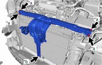
13. INSTALL UPPER RADIATOR SUPPORT SUB-ASSEMBLY
| (a) Install the upper radiator support sub-assembly with the 5 bolts. Torque: for bolt A : 31 N·m {316 kgf·cm, 23 ft·lbf} for bolt B : 12.5 N·m {127 kgf·cm, 9 ft·lbf} |
|
(b) Install the 2 radiator support sub-assemblies to the upper radiator support sub-assembly with the 2 bolts.
Torque:
19 N·m {194 kgf·cm, 14 ft·lbf}
(c) Attach the 3 clamps and connect the 2 connectors, and wire harness to the upper radiator support sub-assembly.
(d) Attach the 3 clamps and connect the front radiator side air guide plate LH.
(e) Attach the 3 clamps and install the front radiator side air guide plate RH.
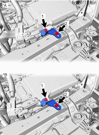
14. INSTALL NO. 6 INVERTER BRACKET
(a) Temporarily install the No. 6 inverter bracket to the upper radiator support sub-assembly with the 2 bolts.
| (b) Tighten the 2 bolts in the order shown in the illustration. Torque: 10.5 N·m {107 kgf·cm, 8 ft·lbf} |
|
15. CONNECT HOOD LOCK ASSEMBLY
(a) Attach the clamp and connect the hood lock control cable assembly to the upper radiator support sub-assembly.
(b) Connect the hood lock assembly to the upper radiator support with the 3 bolts.
Torque:
8.0 N·m {82 kgf·cm, 71 in·lbf}
(c) Attach the 2 clamps and connect the hood lock connector.
16. INSTALL FRONT BUMPER REINFORCEMENT SUB-ASSEMBLY
Click here .gif)
17. ADD ENGINE COOLANT
Click here
18. INSPECT FOR COOLANT LEAK
Click here
READ NEXT:
 Relay
Relay
On-vehicle InspectionON-VEHICLE INSPECTION PROCEDURE 1. INSPECT COOLING FAN RELAY (FAN NO. 1) (a) Measure the resistance according to the value(s) in the table below. Standard Resistance: Test
Thermostat
ComponentsCOMPONENTS ILLUSTRATION *1 THERMOSTAT *2 WATER INLET *3 GASKET - - N*m (kgf*cm, ft.*lbf): Specified torque ● Non-reusable part RemovalREMOVAL PROCEDURE
SEE MORE:
Freeze Frame Data
FREEZE FRAME DATA DESCRIPTION (a) When a pre-collision system DTC is stored, the forward recognition camera stores the current vehicle (ECU or sensor) state as Freeze Frame Data. CHECK FREEZE FRAME DATA (a) Connect the Techstream to the DLC3. (b) Turn the power switch on (IG). (c) Turn the Techstrea
Drive Motor "A" Inverter Performance (P0A78-128)
DTC SUMMARY MALFUNCTION DESCRIPTION This DTC indicates that a large current flowed through the inverter for the motor. The cause of this malfunction may be one of the following: Area Main Malfunction Description Step Inverter low-voltage circuit The connectors are not connected properly
