Lexus NX: Front Passenger Side Power Mirror cannot be Adjusted with Power Mirror Switch
DESCRIPTION
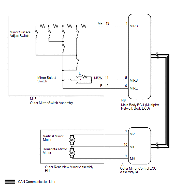
When the outer mirror switch assembly mirror surface adjust switch (up/down/left/right) is operated, up/down/left/right signals are received by the main body ECU (multiplex network body ECU). The main body ECU (multiplex network body ECU) sends the received signals to the outer mirror control ECU assembly RH via CAN communication. The outer mirror control ECU assembly RH receives the remote mirror selection signal and up/down/left/right signals and operates the outer rear view mirror assembly RH up/down/left/right based on the signals.
WIRING DIAGRAM
CAUTION / NOTICE / HINT
NOTICE:
-
First perform the communication function inspections in How to Proceed with Troubleshooting to confirm that there are no CAN communication malfunctions before troubleshooting this problem.
Click here
.gif)
-
If the main body ECU (multiplex network body ECU) is replaced, refer to Registration.
Click here
PROCEDURE
| 1. | READ VALUE USING TECHSTREAM (OUTER MIRROR SWITCH ASSEMBLY) |
(a) Using the Techstream, read the Data List.
Click here
| Tester Display | Measurement Item | Range | Normal Condition | Diagnostic Note |
|---|---|---|---|---|
| Mirror Selection SW (R) | Mirror select switch signal for RH mirror | OFF or ON | OFF: Mirror select switch off ON: Mirror select switch R switch on | - |
| Mirror Position SW (R) | Mirror surface adjust switch signal (Right) | OFF or ON | OFF: Mirror surface adjust switch not pressed right ON: Mirror surface adjust switch pressed right | Check with the mirror select switch R switch on |
| Mirror Position SW (L) | Mirror surface adjust switch signal (Left) | OFF or ON | OFF: Mirror surface adjust switch not pressed left ON: Mirror surface adjust switch pressed left | Check with the mirror select switch R switch on |
| Mirror Position SW (Up) | Mirror surface adjust switch signal (Up) | OFF or ON | OFF: Mirror surface adjust switch not pressed up ON: Mirror surface adjust switch pressed up | Check with the mirror select switch R switch on |
| Mirror Position SW (Dwn) | Mirror surface adjust switch signal (Down) | OFF or ON | OFF: Mirror surface adjust switch not pressed down ON: Mirror surface adjust switch pressed down | Check with the mirror select switch R switch on |
| Tester Display |
|---|
| Mirror Selection SW (R) |
| Mirror Position SW (R) |
| Mirror Position SW (L) |
| Mirror Position SW (Up) |
| Mirror Position SW (Dwn) |
OK:
The display is as specified in the normal condition column.
| NG | .gif) | GO TO STEP 3 |
|
.gif)
| 2. | INSPECT OUTER REAR VIEW MIRROR ASSEMBLY RH |
(a) Remove the outer rear view mirror assembly RH.
Click here
(b) Inspect the outer rear view mirror assembly RH.
Click here
| OK | | REPLACE OUTER MIRROR CONTROL ECU ASSEMBLY RH |
| NG | | REPLACE OUTER REAR VIEW MIRROR ASSEMBLY RH |
| 3. | INSPECT OUTER MIRROR SWITCH ASSEMBLY |
(a) Remove the outer mirror switch assembly.
Click here
(b) Inspect the outer mirror switch assembly.
Click here
| NG | | REPLACE OUTER MIRROR SWITCH ASSEMBLY |
|
| 4. | CHECK HARNESS AND CONNECTOR (OUTER MIRROR SWITCH ASSEMBLY - MAIN BODY ECU [MULTIPLEX NETWORK BODY ECU]) |
(a) Disconnect the M13 outer mirror switch assembly connector.
(b) Disconnect the I49 main body ECU (multiplex network body ECU) connector.
(c) Measure the resistance according to the value(s) in the table below.
Standard Resistance:
| Tester Connection | Condition | Specified Condition |
|---|---|---|
| M13-13 (M+) - I49-4 (MIRB) | Always | Below 1 Ω |
| M13-14 (MSW) - I49-5 (MIRS) | Always | Below 1 Ω |
| M13-12 (E) - I49-6 (MIRE) | Always | Below 1 Ω |
| M13-13 (M+) or I49-4 (MIRB) - Body ground | Always | 10 kΩ or higher |
| M13-14 (MSW) or I49-5 (MIRS) - Body ground | Always | 10 kΩ or higher |
| M13-12 (E) or I49-6 (MIRE) - Body ground | Always | 10 kΩ or higher |
| OK | | REPLACE MAIN BODY ECU (MULTIPLEX NETWORK BODY ECU) |
| NG | | REPAIR OR REPLACE HARNESS OR CONNECTOR |
READ NEXT:
 Power Mirror cannot be Adjusted with Power Mirror Switch
DESCRIPTION When the outer mirror switch assembly mirror select switch is operated, right/left selection signals are sent to the main body ECU (multiplex network body ECU). The main body ECU (multiple
Mirror Heater does not Operate with Rear Defogger Switch
DESCRIPTION When therear window defogger switch (mirror heater switch) is operated, a mirror heater signal is sent to the air conditioning amplifier assembly via LIN communication. The air conditionin
Power Retractable Mirrors do not Operate with Power Retract Mirror Switch
DESCRIPTION When the outer mirror switch assembly mirror retract switch is operated, deploy/retract signals are sent to the main body ECU (multiplex network body ECU). The main body ECU (multiplex net
SEE MORE:
Installation
INSTALLATION PROCEDURE 1. INSTALL INTEGRATION CONTROL AND PANEL ASSEMBLY (VSC OFF SWITCH) (a) Install the integration control and panel assembly (VSC OFF switch) to the upper rear console panel sub-assembly with the 2 screws. HINT: The locations labeled A in the illustration are tightened togethe
Open in Front Floor Electrical Key Oscillator Circuit (B27A5)
DESCRIPTION The certification ECU (smart key ECU assembly) generates a request signal and transmits the signal to the No. 1 indoor electrical key antenna assembly (front floor). For the No. 1 indoor electrical key antenna assembly (front floor) to detect when the electrical key transmitter sub-assem
