Lexus NX: Fuel Pump Ecu
Components
COMPONENTS
ILLUSTRATION
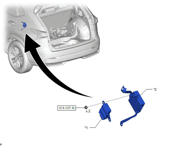
| *1 | FUEL PUMP CONTROL ECU ASSEMBLY | *2 | PARKING BRAKE ECU ASSEMBLY |
.png) | N*m (kgf*cm, ft.*lbf): Specified torque | - | - |
Removal
REMOVAL
PROCEDURE
1. REMOVE PARKING BRAKE ECU ASSEMBLY
Click here .gif)
2. REMOVE FUEL PUMP CONTROL ECU ASSEMBLY
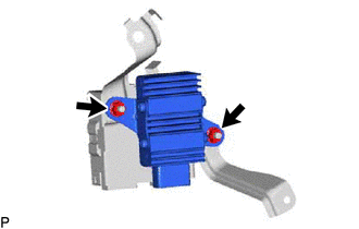
| (a) Remove the 2 nuts and fuel pump control ECU assembly. NOTICE: Do not reuse the fuel pump control ECU assembly if it has been dropped or subjected to a severe impact. |
|
Installation
INSTALLATION
PROCEDURE
1. INSTALL FUEL PUMP CONTROL ECU ASSEMBLY
(a) Install the fuel pump control ECU assembly with the 2 nuts.
Torque:
12.5 N·m {127 kgf·cm, 9 ft·lbf}
NOTICE:
Do not reuse the fuel pump control ECU assembly if it has been dropped or subjected to a severe impact.
2. INSTALL PARKING BRAKE ECU ASSEMBLY
Click here .gif)
READ NEXT:
 Fuel Sender Gauge Assembly
ComponentsCOMPONENTS ILLUSTRATION *1 FUEL SENDER GAUGE ASSEMBLY - - N*m (kgf*cm, ft.*lbf): Specified torque - - RemovalREMOVAL PROCEDURE 1. REMOVE FUEL TANK ASSEMBLY Click he
Parts Location
PARTS LOCATION ILLUSTRATION *1 FUEL INJECTOR ASSEMBLY *2 FUEL PUMP *3 FUEL SENDER GAUGE ASSEMBLY *4 EFI-MAIN RELAY *5 EFI-MAIN NO. 2 RELAY *6 ECM *7 FUEL PUMP CONTR
SEE MORE:
Communication Malfunction between ECUs Connected by LIN (B2785)
DESCRIPTION The certification ECU intermittently monitors the LIN communication bus between the components related to certification. DTC B2785 is stored when a malfunction in the LIN communication bus between the components related to certification is detected 3 times consecutively. DTC No. Det
Terminals Of Ecu
TERMINALS OF ECU CHECK STEREO COMPONENT EQUALIZER ASSEMBLY (a) Measure the voltage and resistance according to the value(s) in the table below. Terminal No. (Symbol) Wiring Color Terminal Description Condition Specified Condition I117-1 (GND) - Body ground W-B - Body ground Groun
