Lexus NX: Parts Location
PARTS LOCATION
ILLUSTRATION
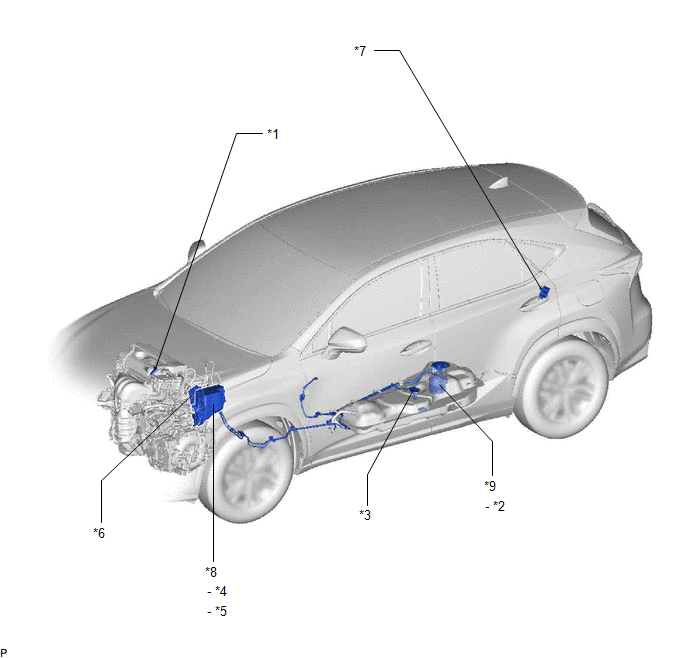
| *1 | FUEL INJECTOR ASSEMBLY | *2 | FUEL PUMP |
| *3 | FUEL SENDER GAUGE ASSEMBLY | *4 | EFI-MAIN RELAY |
| *5 | EFI-MAIN NO. 2 RELAY | *6 | ECM |
| *7 | FUEL PUMP CONTROL ECU ASSEMBLY | *8 | NO. 1 ENGINE ROOM RELAY BLOCK AND JUNCTION BLOCK ASSEMBLY - EFI-MAIN NO. 1 FUSE - EFI-MAIN NO. 2 FUSE - IGN FUSE |
| *9 | FUEL SUCTION TUBE ASSEMBLY | - | - |
READ NEXT:
 System Diagram
SYSTEM DIAGRAM
On-vehicle Inspection
ON-VEHICLE INSPECTION PROCEDURE 1. CHECK FUEL PUMP OPERATION AND INSPECT FOR FUEL LEAK (a) Check fuel pump operation. (1) Connect the Techstream to the DLC3. (2) Turn the power switch on (IG). NOTICE:
SEE MORE:
Inspection
INSPECTION PROCEDURE 1. INSPECT FRONT DOOR LOCK ASSEMBLY LH (a) Check the door lock motor operation. (1) Apply auxiliary battery voltage to the motor connector and check the operation of the door lock motor. OK: Measurement Condition Specified Condition Auxiliary battery positive (+) â†
Disposal
DISPOSAL CAUTION / NOTICE / HINT CAUTION: Before performing pre-disposal deployment of any SRS part, review and closely follow all applicable environmental and hazardous material regulations. Pre-disposal deployment may be considered hazardous material treatment. PROCEDURE 1. PRECAUTION CAUTION:
© 2016-2026 Copyright www.lexunx.com
