Lexus NX: Fuel Sender Gauge Assembly
Components
COMPONENTS
ILLUSTRATION
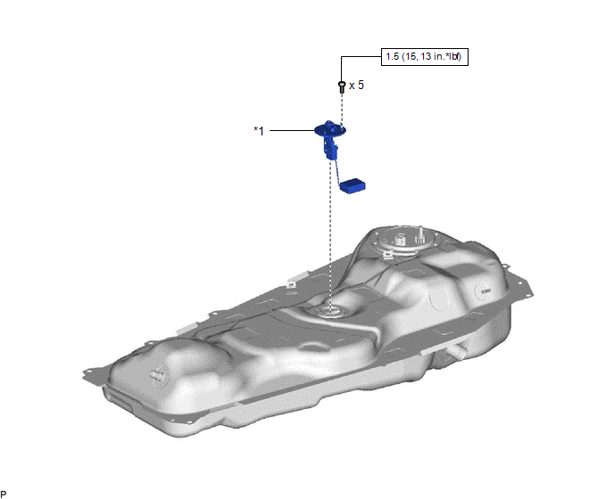
| *1 | FUEL SENDER GAUGE ASSEMBLY | - | - |
.png) | N*m (kgf*cm, ft.*lbf): Specified torque | - | - |
Removal
REMOVAL
PROCEDURE
1. REMOVE FUEL TANK ASSEMBLY
Click here .gif)
2. REMOVE FUEL SENDER GAUGE ASSEMBLY
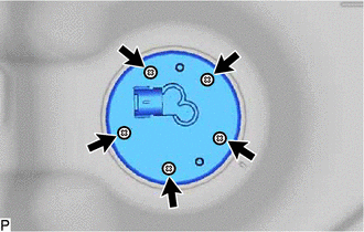
| (a) Remove the 5 screws and fuel sender gauge assembly from the fuel tank assembly. |
|
Inspection
INSPECTION
PROCEDURE
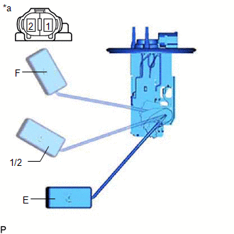
1. INSPECT FUEL SENDER GAUGE ASSEMBLY
(a) Check that the float moves smoothly between F and E.
| (b) Measure the resistance according to the value(s) in the table below. Standard Resistance:
If the value is not as specified, replace the fuel sender gauge assembly. |
|
Installation
INSTALLATION
PROCEDURE
1. INSTALL FUEL SENDER GAUGE ASSEMBLY
(a) Install the fuel sender gauge assembly to the fuel tank assembly with the 5 screws.
Torque:
1.5 N·m {15 kgf·cm, 13 in·lbf}
2. INSTALL FUEL TANK ASSEMBLY
Click here .gif)
READ NEXT:
 Parts Location
PARTS LOCATION ILLUSTRATION *1 FUEL INJECTOR ASSEMBLY *2 FUEL PUMP *3 FUEL SENDER GAUGE ASSEMBLY *4 EFI-MAIN RELAY *5 EFI-MAIN NO. 2 RELAY *6 ECM *7 FUEL PUMP CONTR
System Diagram
SYSTEM DIAGRAM
SEE MORE:
Operation Check
OPERATION CHECK CHECK POWER DOOR LOCK OPERATION NOTICE: The operation check below is based on the non-customized initial condition of the vehicle. (a) Check basic functions. (1) Check that all doors lock when the lock side of the door control switch is pressed. (2) Check that all doors unlock when t
Front Fog Light Circuit
DESCRIPTION Illumination of the front fog lights is controlled by the main body ECU (multiplex network body ECU). WIRING DIAGRAM except Sport Package: for Sport Package: CAUTION / NOTICE / HINT NOTICE:
Inspect the fuses for circuits related to this system before performing the following inspect
