Lexus NX: System Diagram
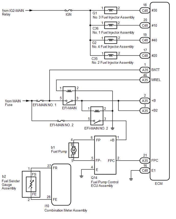
SYSTEM DIAGRAM
READ NEXT:
 On-vehicle Inspection
ON-VEHICLE INSPECTION PROCEDURE 1. CHECK FUEL PUMP OPERATION AND INSPECT FOR FUEL LEAK (a) Check fuel pump operation. (1) Connect the Techstream to the DLC3. (2) Turn the power switch on (IG). NOTICE:
Components
COMPONENTS ILLUSTRATION *1 FRONT FLOOR COVER CENTER LH *2 FUEL TANK VENT HOSE SUB-ASSEMBLY *3 NO. 1 FLOOR UNDER COVER *4 NO. 1 FUEL TANK BAND *5 NO. 2 FUEL TANK BAND - -
SEE MORE:
Installation
INSTALLATION PROCEDURE 1. INSTALL NAVIGATION ANTENNA ASSEMBLY 2. INSTALL NAVIGATION ANTENNA BRACKET (a) Attach the 4 guides to install the navigation antenna assembly as shown in the illustration. (b) Attach the 2 claws to install the navigation antenna assembly. 3. INSTALL ANTENNA CO
Vehicle Specifications have not been Stored (B2451)
DESCRIPTION This DTC is output if the vehicle variation information is not written to the headlight ECU sub-assembly LH. The headlight ECU sub-assembly LH outputs DTC B2451. DTC No. Detection Item DTC Detection Condition Trouble Area B2451 Vehicle Specifications have not been Stored
© 2016-2026 Copyright www.lexunx.com
