Lexus NX: Hybrid Transaxle Oil Seal
Components
COMPONENTS
ILLUSTRATION
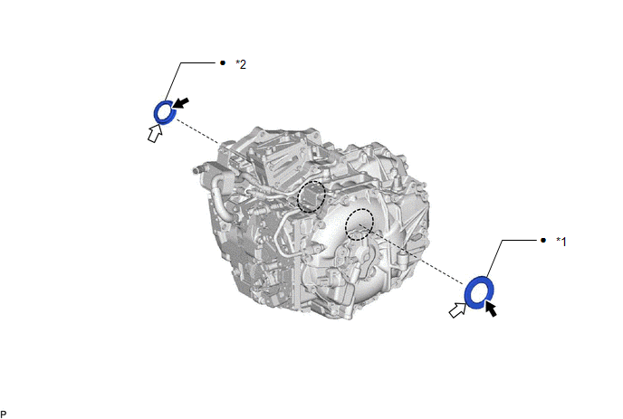
| *1 | FRONT DRIVE SHAFT OIL SEAL LH | *2 | FRONT DRIVE SHAFT OIL SEAL RH |
| ● | Non-reusable part | .png) | MP grease |
.png) | ATF WS | - | - |
Replacement
REPLACEMENT
PROCEDURE
1. REMOVE FRONT DRIVE SHAFT
Click here .gif)
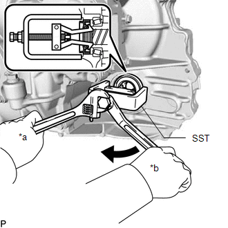
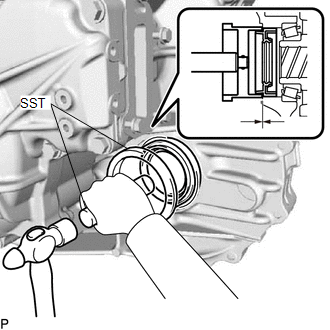
2. REMOVE FRONT DRIVE SHAFT OIL SEAL LH
| (a) Using SST, remove the front drive shaft oil seal LH from the hybrid vehicle transaxle assembly. SST: 09514-35011 |
|
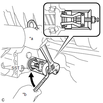
3. REMOVE FRONT DRIVE SHAFT OIL SEAL RH
| (a) Using SST, remove the front drive shaft oil seal RH from the hybrid vehicle transaxle assembly. SST: 09612-30012 |
|
4. INSTALL FRONT DRIVE SHAFT OIL SEAL RH
(a) Coat the outside edge of a new front drive shaft oil seal RH with ATF.
| (b) Using SST and a hammer, install the front drive shaft oil seal RH to the hybrid vehicle transaxle assembly. SST: 09710-30050 SST: 09950-70010 09951-07150 Oil Seal Installation Depth: -0.5 to 0.5 mm (-0.0197 to 0.0196 in.) |
|
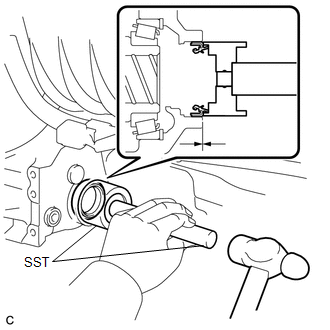
(c) Coat the lip of the front drive shaft oil seal RH with MP grease.
5. INSTALL FRONT DRIVE SHAFT OIL SEAL LH
(a) Coat the outside edge of a new front drive shaft oil seal LH with ATF.
| (b) Using SST and a hammer, install the front drive shaft oil seal LH to the hybrid vehicle transaxle assembly. SST: 09223-15020 SST: 09950-70010 09951-07150 Oil Seal Installation Depth: -0.5 to 0.5 mm (-0.0197 to 0.0196 in.) |
|
(c) Coat the lip of the front drive shaft oil seal LH with MP grease.
6. INSTALL FRONT DRIVE SHAFT
Click here
READ NEXT:
 Hybrid Transaxle System
On-vehicle InspectionON-VEHICLE INSPECTION PROCEDURE 1. INSPECT FLUID PRESSURE OF OIL PUMP (a) Remove the rear engine under cover LH. Click here (b) Remove the fluid pump cover plug and O-ring
Components
COMPONENTS ILLUSTRATION *1 SERVICE PLUG GRIP *2 BATTERY SERVICE HOLE COVER *3 HYBRID BATTERY SERVICE PLUG COVER - - N*m (kgf*cm, ft.*lbf): Specified torque - - ILLUST
SEE MORE:
On-vehicle Inspection
ON-VEHICLE INSPECTION CAUTION / NOTICE / HINT CAUTION: Be sure to follow the correct removal and installation procedures of the door side airbag sensors. PROCEDURE 1. INSPECT DOOR SIDE AIRBAG SENSOR (for Vehicle not Involved in Collision) (a) Perform a diagnostic system check. Click here 2. INSPE
On-vehicle Inspection
ON-VEHICLE INSPECTION PROCEDURE 1. INSPECT STOP LIGHT SWITCH ASSEMBLY (a) Disconnect the stop light switch assembly connector. *a Front view of wire harness connector (to Stop Light Switch Assembly) (b) Measure the voltage and resistance on the wire harness side connector
