Lexus NX: On-vehicle Inspection
ON-VEHICLE INSPECTION
PROCEDURE
1. INSPECT STOP LIGHT SWITCH ASSEMBLY
| (a) Disconnect the stop light switch assembly connector. |
|
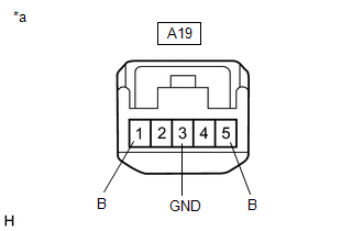
(b) Measure the voltage and resistance on the wire harness side connector according to the value(s) in the table below.
Standard Voltage:
| Tester Connection | Condition | Specified Condition |
|---|---|---|
| A1-1 (B) - A1-3 (GND) | Always | 11 to 14 V |
| A1-5 (B) - A1-3 (GND) | Always | 11 to 14 V |
Standard Resistance:
| Tester Connection | Condition | Specified Condition |
|---|---|---|
| A1-3 (GND) - Body ground | Always | Below 1 Ω |
If the result is not as specified, repair or replace the wire harness or connector.
(c) Reconnect the stop light switch assembly connector.
| (d) w/o Dynamic Radar Cruise Control System: Measure the voltage according to the value(s) in the table below. Standard Voltage:
If the result is not as specified, replace the stop light switch assembly. |
|
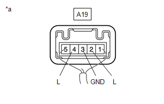
| (e) w/ Dynamic Radar Cruise Control System: Measure the voltage according to the value(s) in the table below. Standard Voltage:
If the result is not as specified, replace the stop light switch assembly. |
|
READ NEXT:
 Removal
REMOVAL PROCEDURE 1. REMOVE DOOR SCUFF PLATE ASSEMBLY LH Click here 2. REMOVE COWL SIDE TRIM BOARD LH Click here 3. REMOVE NO. 1 INSTRUMENT PANEL UNDER COVER SUB-ASSEMBLY Click here 4. R
Installation
INSTALLATION PROCEDURE 1. INSTALL STOP LIGHT SWITCH ASSEMBLY (a) Turn the stop light switch assembly in the clockwise direction until it reaches the standard shaft protrusion amount and temporarily
SEE MORE:
Problem Symptoms Table
PROBLEM SYMPTOMS TABLE NOTICE: If the main body ECU (multiplex network body ECU) is replaced, refer to Registration. Click here HINT:
Use the table below to help determine the cause of problem symptoms. If multiple suspected areas are listed, the potential causes of the symptoms are listed in
Components
COMPONENTS ILLUSTRATION *A w/o Performance Damper *B w/ Performance Damper *1 AIR CLEANER CASE SUB-ASSEMBLY *2 AIR CLEANER FILTER ELEMENT SUB-ASSEMBLY *3 OUTER COWL TOP PANEL *4 SUSPENSION TOWER DAMPER N*m (kgf*cm, ft.*lbf): Specified torque - - ILLUSTRATI
