-
Communication stop for "Hybrid Vehicle Control" is indicated on "Communication Bus Check".
Click here
.gif)
-
Communication system DTCs (DTCs that start with U) that are output correspond to "Hybrid Vehicle Control ECU Communication Stop Mode" in "DTC Combination Table".
Click here
Lexus NX: Hybrid Vehicle Control ECU Communication Stop Mode
Lexus NX Service Manual / Power Source & Network / Networking / Can Communication System / Hybrid Vehicle Control ECU Communication Stop Mode
DESCRIPTION
| Detection Item | Symptom | Trouble Area |
|---|---|---|
| Hybrid Vehicle Control ECU Communication Stop Mode | Any of the following conditions are met: |
|
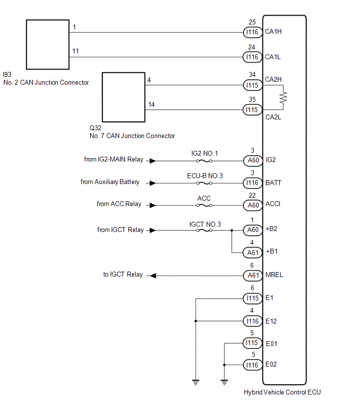
WIRING DIAGRAM
CAUTION / NOTICE / HINT
CAUTION:
When performing the confirmation driving pattern, obey all speed limits and traffic laws.
NOTICE:
- Inspect the fuses for circuits related to this system before performing the following inspection procedure.
- Before measuring the resistance of the CAN bus, turn the power switch off and leave the vehicle for 1 minute or more without operating the key, switches or opening or closing the doors. After that, disconnect the cable from the negative (-) auxiliary battery terminal and leave the vehicle for 1 minute or more before measuring the resistance.
-
After turning the power switch off, waiting time may be required before disconnecting the cable from the negative (-) auxiliary battery terminal.
Click here
-
When disconnecting and reconnecting the auxiliary battery.
Click here
HINT:
When disconnecting and reconnecting the auxiliary battery, there is an automatic learning function that completes learning when the respective system is used.
Click here
-
Some parts must be initialized and set when replacing or removing and installing parts.
Click here
-
Because the order of diagnosis is important to allow correct diagnosis, make sure to begin troubleshooting using How to Proceed with Troubleshooting when CAN communication system related DTCs are output.
Click here
-
After performing repairs, perform the DTC check procedure and confirm that the DTCs are not output again.
DTC check procedure: Turn the power switch on (IG) and wait for 1 minute or more. Then operate the suspected malfunctioning system and drive the vehicle at 60 km/h (37 mph) or more for 5 minutes or more.
-
After the repair, perform CAN Bus Check and check that all the ECUs and sensors connected to the CAN communication system are displayed as normal.
Click here
HINT:
- Operating the power switch, any other switches or a door triggers related ECU and sensor communication on the CAN. This communication will cause the resistance value to change.
- Even after DTCs are cleared, if a DTC is stored again after driving the vehicle for a while, the malfunction may be occurring due to vibration of the vehicle. In such a case, wiggling the ECUs or wire harness while performing the inspection below may help determine the cause of the malfunction.
PROCEDURE
| 1. | CHECK FOR OPEN IN CAN BUS WIRE (HYBRID VEHICLE CONTROL ECU MAIN WIRE AND BRANCH WIRE) |
(a) Disconnect the cable from the negative (-) auxiliary battery terminal.
| (b) Disconnect the hybrid vehicle control ECU connectors. |
|
(c) Measure the resistance according to the value(s) in the table below.
Standard Resistance:
Bus 2 Branch Wire| Tester Connection | Condition | Specified Condition |
|---|---|---|
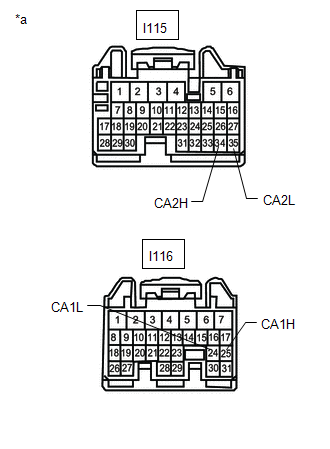
| I115-34 (CA2H) - I115-35 (CA2L) | Cable disconnected from negative (-) auxiliary battery terminal | 54 to 69 Ω |
| Tester Connection | Condition | Specified Condition |
|---|---|---|
| I116-25 (CA1H) - I116-24 (CA1L) | Cable disconnected from negative (-) auxiliary battery terminal | 108 to 132 Ω |
| Result | Proceed to |
|---|---|
| OK | A |
| NG (Bus 2 branch wire) | B |
| NG (Bus 5 main wire) | C |
| B | .gif) | REPAIR OR REPLACE CAN BRANCH WIRE OR CONNECTOR |
| C | | REPAIR OR REPLACE CAN MAIN WIRE OR CONNECTOR |
|
.gif)
| 2. | CHECK HARNESS AND CONNECTOR (POWER SOURCE CIRCUIT) |
(a) Disconnect the hybrid vehicle control ECU connectors.
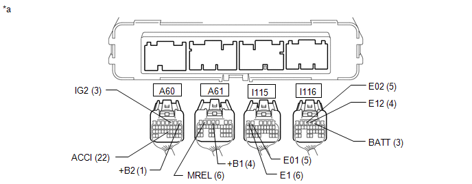
| *a | Rear view of wire harness connector (to Hybrid Vehicle Control ECU) | - | - |
(b) Measure the resistance according to the value(s) in the table below.
Standard Resistance:
| Tester Connection | Condition | Specified Condition |
|---|---|---|
| I115-6 (E1) - Body ground | Cable disconnected from negative (-) auxiliary battery terminal | Below 1 Ω |
| I115-5 (E01) - Body ground | Cable disconnected from negative (-) auxiliary battery terminal | Below 1 Ω |
| I116-4 (E12) - Body ground | Cable disconnected from negative (-) auxiliary battery terminal | Below 1 Ω |
| I116-5 (E02) - Body ground | Cable disconnected from negative (-) auxiliary battery terminal | Below 1 Ω |
(c) Reconnect the cable to the negative (-) auxiliary battery terminal.
(d) Measure the voltage according to the value(s) in the table below.
Standard Voltage:
| Tester Connection | Condition | Specified Condition |
|---|---|---|
| I116-3 (BATT) - Body ground | Power switch off | 11 to 14 V |
| A60-1 (+B2) - Body ground | Auxiliary battery voltage applied to terminal A61-6 (MREL) | 11 to 14 V |
| A61-4 (+B1) - Body ground | Auxiliary battery voltage applied to terminal A61-6 (MREL) | 11 to 14 V |
| A60-3 (IG2) - Body ground | Power switch on (IG) | 11 to 14 V |
| Power switch off | Below 1 V | |
| A60-22 (ACCI) - Body ground | Power switch on (ACC) | 11 to 14 V |
| Power switch off | Below 1 V |
| OK | | REPLACE HYBRID VEHICLE CONTROL ECU |
| NG | | REPAIR OR REPLACE HARNESS OR CONNECTOR (POWER SOURCE CIRCUIT) |
READ NEXT:
 Skid Control ECU Communication Stop Mode
DESCRIPTION Detection Item Symptom Trouble Area Skid Control ECU Communication Stop Mode Any of the following conditions are met:
Communication stop for "Skid Control (ABS/VSC/TRAC)" i
Clearance Warning ECU Communication Stop Mode
DESCRIPTION Detection Item Symptom Trouble Area Clearance Warning ECU Communication Stop Mode Any of the following conditions are met:
Communication stop for "Clearance Warning (Intuit
Air Conditioning Amplifier Communication Stop Mode
DESCRIPTION Detection Item Symptom Trouble Area Air Conditioning Amplifier Communication Stop Mode Any of the following conditions are met:
Communication stop for "Air Conditioning Amp
SEE MORE:
Security Horn Circuit
DESCRIPTION When the theft deterrent system is switched from the armed state to the alarm sounding state, the main body ECU (multiplex network body ECU) transmits a signal to cause the security horn to sound at intervals of 0.4 seconds. WIRING DIAGRAM CAUTION / NOTICE / HINT NOTICE:
Inspect the
Removal
REMOVAL CAUTION / NOTICE / HINT HINT:
Use the same procedure for the RH and LH sides.
The procedure listed below is for the LH side.
PROCEDURE 1. PRECAUTION Click here 2. REMOVE FRONT DOOR TRIM COVER LH Click here 3. REMOVE FRONT DOOR INSIDE HANDLE BEZEL PLUG LH Click here 4. REMOVE
© 2016-2026 Copyright www.lexunx.com
