Lexus NX: Removal
REMOVAL
PROCEDURE
1. DISABLE AUTOAWAY/RETURN FUNCTION (for Power Tilt and Power Telescopic Steering Column)
(a) Disable the autoaway/return function by changing the customize parameter.
Click here .gif)
CAUTION:
Record the current customize parameter setting (whether the autoaway/return function is enabled or disabled) in order to restore the current setting after finishing the operation.
HINT:
Performing the above operation causes the autoaway/return function to be disabled when the power switch is turned off.
(b) Turn the power switch on (IG). Operate the tilt and telescopic switch to fully extend and lower the steering column assembly.
(c) Turn the power switch off.
2. REMOVE NO. 3 DECK BOARD SUB-ASSEMBLY
Click here
3. REMOVE REAR DECK FLOOR BOX
Click here
4. REMOVE DECK FLOOR BOX LH
Click here
5. PRECAUTION
CAUTION:
Be sure to read Precoution thoroughly before serving.
Click here
NOTICE:
After turning the power switch off, there may be a waiting time before disconnecting the negative (-) auxiliary battery terminal.
Click here
6. DISCONNECT CABLE FROM NEGATIVE AUXILIARY BATTERY TERMINAL
CAUTION:
- Wait at least 90 seconds after disconnecting the cable from the negative (-) auxiliary battery terminal to disable the SRS system.
- If the airbag deploys for any reason. it may cause a serious accident.
7. REMOVE LOWER INSTRUMENT PANEL SUB-ASSEMBLY
Click here
8. REMOVE GLOVE BOX LIGHT ASSEMBLY
(a) Using a screwdriver, detach the 2 claws and remove the glove box light assembly.
HINT:
Tape the screwdriver tip before use.
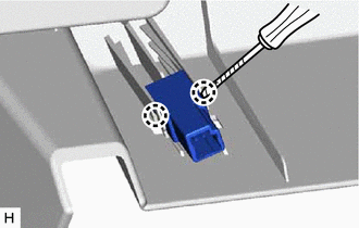
.png) | Protective Tape |
READ NEXT:
 Inspection
INSPECTION PROCEDURE 1. INSPECT GLOVE BOX LIGHT ASSEMBLY (a) Apply battery voltage to the connector and check the light illumination condition. OK: Measurement Condition Specified Condition
Installation
INSTALLATION PROCEDURE 1. INSTALL GLOVE BOX LIGHT ASSEMBLY (a) Attach the 2 claws to install the glove box light assembly. 2. INSTALL LOWER INSTRUMENT PANEL SUB-ASSEMBLY Click here 3.
SEE MORE:
System Description
SYSTEM DESCRIPTION REAR POWER SEAT CONTROL SYSTEM DESCRIPTION
This system has the following functions: reclining, folding and return, and jam protection.
Both the left and right seats are equipped with this system. Each system operates independently.
FUNCTIONS OF MAIN COMPONENTS Component
Removal
REMOVAL CAUTION / NOTICE / HINT HINT:
Use the same procedure for the RH and LH sides.
The procedure listed below is for the LH side.
PROCEDURE 1. REMOVE REAR DOOR TRIM COVER LH Click here 2. REMOVE REAR DOOR INSIDE HANDLE BEZEL PLUG LH Click here 3. REMOVE REAR POWER WINDOW REGULATOR S
