- Power switch on (IG)
- Climate control switch (for Front Passenger Side) on
Lexus NX: Terminals Of Ecu
TERMINALS OF ECU
CHECK AIR CONDITIONING AMPLIFIER ASSEMBLY
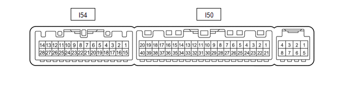
(a) Disconnect the I50 air conditioning amplifier assembly connector.
(b) Measure the voltage and resistance according to the value(s) in the table below.
| Tester Connection | Wiring Color | Terminal Description | Condition | Specified Condition |
|---|---|---|---|---|
| I50-1 (IG+) - Body ground | SB - Body ground | IG power supply | Power switch off | Below 1 V |
| Power switch on (IG) | 11 to 14 V | |||
| I50-14 (GND) - Body ground | W-B - Body ground | Ground | Always | Below 1 Ω |
| I50-21 (B) - Body ground | GR - Body ground | Battery power supply | Power switch off | 11 to 14 V |
(c) Reconnect the I50 air conditioning amplifier assembly connector.
(d) Check for pulses according to the value(s) in the table below.
| Tester Connection | Wiring Color | Terminal Description | Condition | Specified Condition |
|---|---|---|---|---|
| I50-37 (LIN1) - Body ground | B - Body ground | Climate control switch signal (LIN) | Power switch on (IG) | Pulse generation |
| I54-10 (SVPB) - Body ground | GR - Body ground | Seat blower drive signal (for Front Passenger Side) | | Pulse generation (See waveform) |
| I54-11 (SVDB) - Body ground | Y - Body ground | Seat blower drive signal (for Driver Side) |
| Pulse generation (See waveform) |
(1) Waveform (Reference):
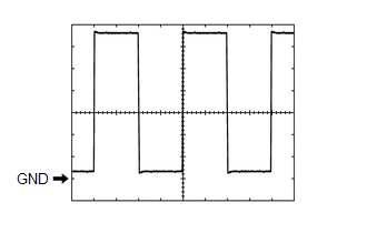 Measurement Condition
 | Item | Content |
|---|---|
| Tester Connection | I54-10 (SVPB) - Body ground |
| Tool Setting | 1 V/DIV., 1 ms/DIV. |
| Vehicle Condition |
|
| Item | Content |
|---|---|
| Tester Connection | I54-11 (SVDB) - Body ground |
| Tool Setting | 1 V/DIV., 1 ms/DIV. |
| Vehicle Condition |
|
AIR CONDITIONING CONTROL ASSEMBLY
Click here .gif)
READ NEXT:
 Diagnosis System
DIAGNOSIS SYSTEM CHECK DLC3 (a) Check the DLC3. Click here INSPECT AUXILIARY BATTERY VOLTAGE (a) Check the auxiliary battery voltage. Standard voltage: 11 to 14 V (power switch off) If the voltage
Climate Control System does not Operate on Driver Side
DESCRIPTION The air conditioning control assembly sends operation signals to the air conditioning amplifier assembly via the LIN communication line. The air conditioning amplifier assembly actives the
Climate Control System does not Operate on Passenger Side
DESCRIPTION The air conditioning control assembly sends operation signals to the air conditioning amplifier assembly via the LIN communication line. The air conditioning amplifier assembly actives the
SEE MORE:
Data List / Active Test
DATA LIST / ACTIVE TEST DATA LIST HINT: Using the Techstream to read the Data List allows the values or states of switches, sensors, actuators and other items to be read without removing any parts. This non-intrusive inspection can be very useful because intermittent conditions or signals may be dis
Inspection
INSPECTION PROCEDURE 1. INSPECT CAMSHAFT TIMING OIL CONTROL VALVE ASSEMBLY (a) Measure the resistance according to the value(s) in the table below. Standard Resistance: Tester Connection Condition Specified Condition 1 - 2 20°C (68°F) 6.9 to 7.9 Ω If the result is not as specif
© 2016-2026 Copyright www.lexunx.com
