Lexus NX: Inspection
INSPECTION
PROCEDURE
1. INSPECT OUTER MIRROR SWITCH ASSEMBLY (w/ Memory)
| (a) Check the mirror retract switch. (1) Measure the resistance according to the value(s) in the table below. Standard Resistance:
If the result is not as specified, replace the outer mirror switch assembly. |
|
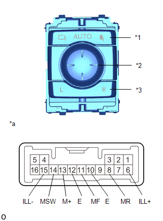
(b) Check the mirror select switch.
(1) Measure the resistance according to the value(s) in the table below.
Standard Resistance:
| Tester Connection | Condition | Specified Condition |
|---|---|---|
| 12 (E) - 14 (MSW) | R | Below 10 Ω |
| L | 90 to 110 Ω | |
| Off | 10 kΩ or higher |
If the result is not as specified, replace the outer mirror switch assembly.
(c) Check the mirror adjust switch.
(1) Select the mirror select switch to the L position or R position.
(2) Measure the resistance according to the value(s) in the table below.
Standard Resistance:
| Tester Connection | Condition | Specified Condition |
|---|---|---|
| 12 (E) - 13 (M+) | Mirror adjust switch pressed up | 90 to 110 Ω |
| Off | 10 kΩ or higher | |
| Mirror adjust switch pressed down | 437 to 503 Ω | |
| Off | 10 kΩ or higher | |
| Mirror adjust switch pressed left | 744 to 856 Ω | |
| Off | 10 kΩ or higher | |
| Mirror adjust switch pressed right | 225 to 275 Ω | |
| Off | 10 kΩ or higher |
If the result is not as specified, replace the outer mirror switch assembly.
(d) Check the switch illumination.
(1) Apply auxiliary battery voltage between the terminals of the light and check the operation of the light.
Standard:
| Auxiliary Battery Connection | Specified Condition |
|---|---|
| Auxiliary Battery positive (+) → 6 (ILL+) Auxiliary Battery negative (-) → 15 (ILL-) | Light comes on |
If the result is not as specified, replace the outer mirror switch assembly.
2. INSPECT OUTER MIRROR SWITCH ASSEMBLY (w/o Memory)
| (a) Check the mirror retract switch. (1) Measure the resistance according to the value(s) in the table below. Standard Resistance:
If the result is not as specified, replace the outer mirror switch assembly. |
|
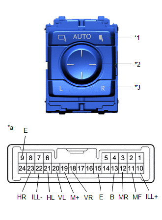
(b) Check the mirror select switch and mirror adjust switch.
(1) Select the mirror select switch to the L position.
(2) Measure the resistance according to the value(s) in the table below.
Standard Resistance (for left side):
| Tester Connection | Condition | Specified Condition |
|---|---|---|
| 20 (VL) - 13 (B) 19 (M+) - 15 (E) | Up | Below 1 Ω |
| Off | 10 kΩ or higher | |
| 20 (VL) - 15 (E) 19 (M+) - 13 (B) | Down | Below 1 Ω |
| Off | 10 kΩ or higher | |
| 21 (HL) - 13 (B) 19 (M+) - 15 (E) | Left | Below 1 Ω |
| Off | 10 kΩ or higher | |
| 21 (HL) - 15 (E) 19 (M+) - 13 (B) | Right | Below 1 Ω |
| Off | 10 kΩ or higher |
If the result is not as specified, replace the outer mirror switch assembly.
(3) Select the mirror select switch to the R position.
(4) Measure the resistance according to the value(s) in the table below.
Standard Resistance (for right side):
| Tester Connection | Condition | Specified Condition |
|---|---|---|
| 18 (VR) - 13 (B) 19 (M+) - 15 (E) | Up | Below 1 Ω |
| Off | 10 kΩ or higher | |
| 18 (VR) - 15 (E) 19 (M+) - 13 (B) | Down | Below 1 Ω |
| Off | 10 kΩ or higher | |
| 23 (HR) - 13 (B) 19 (M+) - 15 (E) | Left | Below 1 Ω |
| Off | 10 kΩ or higher | |
| 23 (HR) - 15 (E) 19 (M+) - 13 (B) | Right | Below 1 Ω |
| Off | 10 kΩ or higher |
If the result is not as specified, replace the outer mirror switch assembly.
(c) Check the switch illumination.
(1) Apply auxiliary battery voltage between the terminals of the light and check the operation of the light.
Standard:
| Auxiliary Battery Connection | Specified Condition |
|---|---|
| Auxiliary Battery positive (+) → 10 (ILL+) Auxiliary Battery negative (-) → 22 (ILL-) | Light comes on |
If the result is not as specified, replace the outer mirror switch assembly.
READ NEXT:
 Installation
INSTALLATION PROCEDURE 1. INSTALL OUTER MIRROR SWITCH ASSEMBLY (a) Attach the 4 claws and install the outer mirror switch assembly. 2. INSTALL POWER WINDOW REGULATOR MASTER SWITCH ASSEMBLY WITH FRONT
Components
COMPONENTS ILLUSTRATION *A for Driver Side *B for Front Passenger Side *1 FRONT DOOR INSIDE HANDLE BEZEL PLUG LH *2 FRONT DOOR TRIM BOARD SUB-ASSEMBLY LH *3 FRONT DOOR TRIM C
SEE MORE:
DCM Communication Stop Mode
DESCRIPTION Detection Item Symptom Trouble Area DCM Communication Stop Mode Any of the following conditions are met:
Communication stop for "DCM" is indicated on the "Communication Bus Check" screen of the Techstream.
Click here
Communication system DTCs (DTCs that start with U)
Disassembly
DISASSEMBLY CAUTION / NOTICE / HINT HINT:
Use the same procedure for the RH and LH sides.
The procedure listed below is for the LH side.
PROCEDURE 1. REMOVE NO. 3 MOULDING TAPE (a) Remove the No. 3 moulding tape. HINT: Do not pull on the No. 3 moulding tape. Instead, roll the tape up with y
