Lexus NX: Components
COMPONENTS
ILLUSTRATION
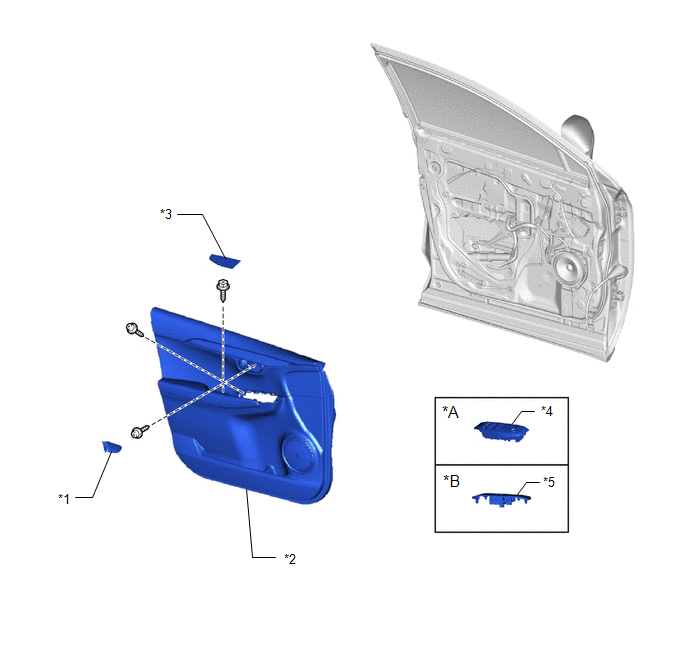
| *A | for Driver Side | *B | for Front Passenger Side |
| *1 | FRONT DOOR INSIDE HANDLE BEZEL PLUG LH | *2 | FRONT DOOR TRIM BOARD SUB-ASSEMBLY LH |
| *3 | FRONT DOOR TRIM COVER LH | *4 | POWER WINDOW REGULATOR MASTER SWITCH ASSEMBLY WITH FRONT DOOR ARMREST BASE PANEL |
| *5 | POWER WINDOW REGULATOR SWITCH ASSEMBLY WITH FRONT DOOR ARMREST BASE PANEL | - | - |
ILLUSTRATION
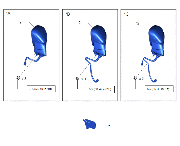
| *A | w/o Memory | *B | w/ Memory |
| *C | w/ Panoramic View Monitor System | - | - |
| *1 | OUTER MIRROR INSTALL HOLE COVER LH | *2 | OUTER REAR VIEW MIRROR ASSEMBLY LH |
.png) | N*m (kgf*cm, ft.*lbf): Specified torque | - | - |
ILLUSTRATION
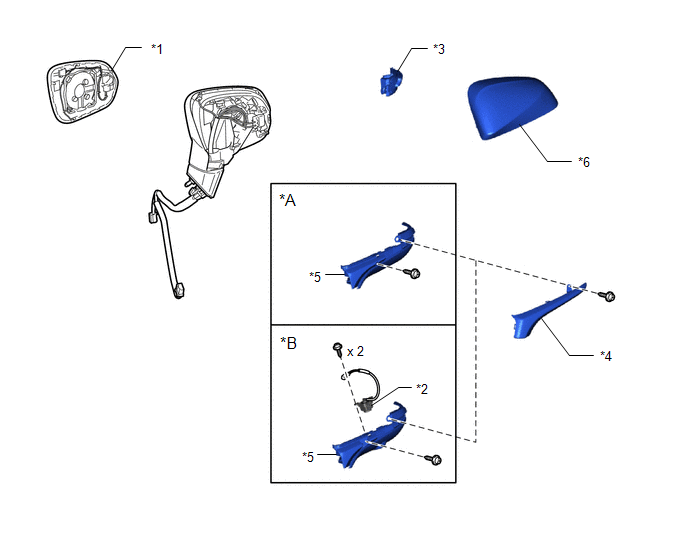
| *A | w/o Panoramic View Monitor System | *B | w/ Panoramic View Monitor System |
| *1 | OUTER MIRROR LH | *2 | SIDE TELEVISION CAMERA ASSEMBLY LH |
| *3 | SIDE TURN SIGNAL LIGHT ASSEMBLY LH | *4 | OUTER MIRROR COVER LH |
| *5 | LOWER OUTER MIRROR COVER LH | *6 | UPPER OUTER MIRROR COVER LH |
ILLUSTRATION
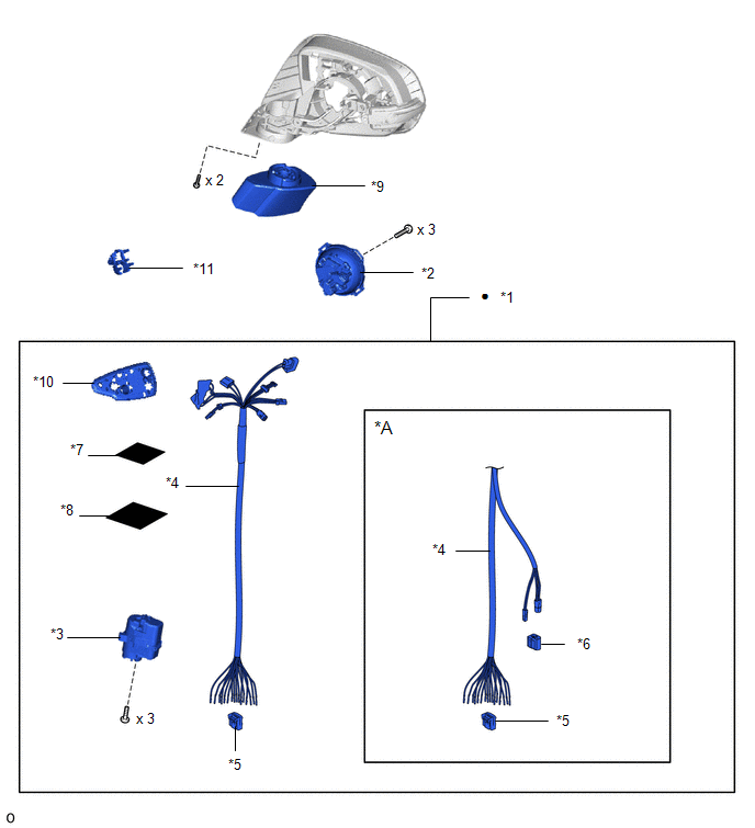
| *A | w/ Memory, w/ Panoramic View Monitor System | - | - |
| *1 | OUTER MIRROR RETRACTOR LH | *2 | ACUTUATOR SUB-ASSEMBLY |
| *3 | FRAME SUB-ASSEMBLY | *4 | HARNESS SUB-ASSEMBLY |
| *5 | CONNECTOR | *6 | ADAPTER |
| *7 | SEAL D | *8 | VINYL SHEET |
| *9 | BASE SUB-ASSEMBLY | *10 | GASKET |
| *11 | HOOK | - | - |
| ● | Non-reusable part | - | - |
READ NEXT:
 Removal
REMOVAL CAUTION / NOTICE / HINT HINT:
Use the same procedure for the RH and LH sides.
The procedure listed below is for the LH side.
PROCEDURE 1. REMOVE FRONT DOOR TRIM COVER LH Click here
Disassembly
DISASSEMBLY CAUTION / NOTICE / HINT HINT:
Use the same procedure for the RH and LH sides.
The procedure listed below is for the LH side.
PROCEDURE 1. REMOVE OUTER MIRROR LH Click here 2. REM
Inspection
INSPECTION PROCEDURE 1. INSPECT OUTER REAR VIEW MIRROR ASSEMBLY LH (a) Check the operation of the mirror surface. (1) Disconnect the outer rear view mirror assembly LH connector. *a
SEE MORE:
Vehicle Approaching Sound ECU Communication Stop Mode
DESCRIPTION Detection Item Symptom Trouble Area Vehicle Approaching Sound ECU Communication Stop Mode Any of the following conditions are met:
Communication stop for "Vehicle Proximity Notification System" is indicated on the "Communication Bus Check" screen of the Techstream.
Click
Lost Communication with "Door Control Module B" (U0200)
DESCRIPTION DTC No. Detection Item DTC Detection Condition Trouble Area DTC Output from U0200 Lost Communication with "Door Control Module B" There is no communication from the outer mirror control ECU assembly RH.
Power source circuit of outer mirror control ECU assembly RH
