Lexus NX: Inspection
INSPECTION
PROCEDURE
1. INSPECT REAR WIPER MOTOR ASSEMBLY
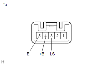
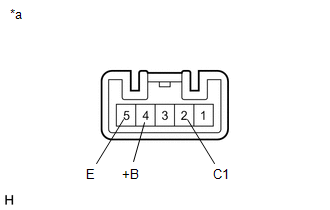
| *a | Component without harness connected (Rear Wiper Motor Assembly) |
(a) Check that the rear wiper motor assembly operates.
NOTICE:
Check that the body ground is connected.
(1) Apply auxiliary battery voltage to the rear wiper motor connector and check the speed of the rear wiper motor assembly.
OK:
| Measurement Condition | Specified Condition |
|---|---|
| Auxiliary battery positive (+) → Terminal 4 (+B) Auxiliary battery negative (-) → Terminal 5 (E) Auxiliary battery negative (-) → Terminal 3 (LS) | Motor operates |
If the result is not as specified, replace the rear wiper motor assembly.
| (b) Check the wiper intermittent operation. NOTICE: Check that the body ground is connected. (1) Apply auxiliary battery voltage to the rear wiper motor connector and check the speed of the rear wiper motor assembly. OK:
If the result is not as specified, replace the rear wiper motor assembly. |
|
READ NEXT:
 Installation
INSTALLATION PROCEDURE 1. INSTALL REAR WIPER MOTOR GROMMET (a) Apply MP grease to the entire circumference of the lip portion of the rear wiper motor grommet. HINT: Do not fill the hole with MP gre
Rear Wiper Rubber
ComponentsCOMPONENTS ILLUSTRATION *1 REAR WIPER BLADE *2 REAR WIPER RUBBER *3 REAR WIPER BACKING PLATE - - ReplacementREPLACEMENT PROCEDURE 1. REMOVE REAR WIPER BLADE (a) Move
SEE MORE:
Components
COMPONENTS ILLUSTRATION *1 HV WATER PUMP BRACKET SUB-ASSEMBLY *2 NO. 1 ENGINE UNDER COVER ASSEMBLY *3 NO. 2 INVERTER COOLING HOSE ASSEMBLY *4 WATER PUMP WITH MOTOR *5 NO. 2 INVERTER COOLING HOSE *6 NO. 3 INVERTER COOLING HOSE *7 WATER PUMP WITH MOTOR CONNECTOR -
Removal
REMOVAL PROCEDURE 1. REMOVE NO. 3 DECK BOARD SUB-ASSEMBLY Click here 2. REMOVE REAR DECK FLOOR BOX Click here 3. REMOVE DECK FLOOR BOX LH Click here 4. PRECAUTION CAUTION: Be sure to read Precaution thoroughly before servicing. Click here NOTICE: After the power switch is turned off, there m
