Lexus NX: Installation
INSTALLATION
PROCEDURE
1. INSTALL REAR WIPER MOTOR GROMMET
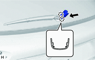
| (a) Apply MP grease to the entire circumference of the lip portion of the rear wiper motor grommet. HINT: Do not fill the hole with MP grease. Only apply MP grease to the grooves of the lip portion. |
|
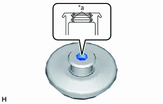
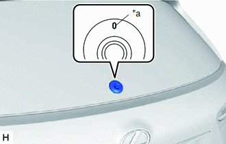
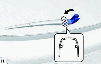
| (b) Install the rear wiper motor grommet with its alignment mark aligned with the top of the vehicle. |
|
2. INSTALL REAR WIPER MOTOR ASSEMBLY
(a) Install the rear wiper motor assembly with the 3 bolts.
Torque:
5.5 N·m {56 kgf·cm, 49 in·lbf}
(b) Connect the connector.
3. INSTALL REAR WIPER ARM AND BLADE ASSEMBLY
| (a) When reinstalling: (1) Clean the rear wiper arm serrations. NOTICE: Do not grind the rear wiper arm serrations. |
|
(b) Using a wire brush, clean the rear wiper motor assembly pivot serrations.
NOTICE:
Do not grind the rear wiper arm serrations.
(c) Turn the power switch on (IG).
(d) Operate the rear wiper motor assembly and stop at the automatic stop (park) position.
(e) Turn the power switch off.
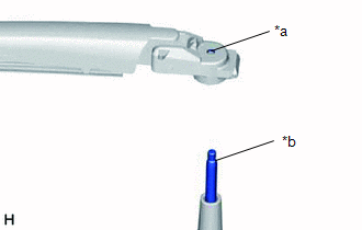
| (f) Align the alignment mark of the back door glass sub-assembly with the edge of the rear wiper arm and blade assembly to install the rear wiper arm and blade assembly. |
|
(g) Install the nut.
Torque:
5.5 N·m {56 kgf·cm, 49 in·lbf}
HINT:
Hold the arm hinge by hand when tightening the nut.
(h) Operate the rear wiper motor assembly while spraying washer fluid on the glass. Make sure that the rear wipers function properly and the wipers do not come into contact with the vehicle body.
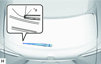
(i) Raise the rear wiper arm 2 times and check that the tip of the rear wiper blade is within the range shown in the illustration.
4. INSTALL REAR WIPER ARM HEAD CAP
| (a) Attach the 2 claws to the rear wiper arm and blade assembly. |
|
| (b) Attach the 2 claws to install the rear wiper arm head cap as shown in the illustration. |
|
5. INSTALL BACK DOOR TRIM BOARD ASSEMBLY
Click here .gif)
6. INSTALL BACK DOOR LOCK COVER (w/ Power Back Door)
Click here
7. INSTALL BACK DOOR LOCK COVER (w/o Power Back Door)
Click here
8. INSTALL BACK DOOR TRIM BASE (w/ Power Back Door)
Click here
9. INSTALL PULL HANDLE (w/ Power Back Door)
Click here
10. INSTALL BACK DOOR FINISH COVER LH (w/o Power Back Door)
Click here
11. INSTALL BACK DOOR FINISH COVER RH (w/o Power Back Door)
Click here
12. INSTALL BACK DOOR SIDE GARNISH LH
Click here
13. INSTALL BACK DOOR SIDE GARNISH RH
Click here
14. INSTALL BACK DOOR CENTER GARNISH
Click here
READ NEXT:
 Rear Wiper Rubber
ComponentsCOMPONENTS ILLUSTRATION *1 REAR WIPER BLADE *2 REAR WIPER RUBBER *3 REAR WIPER BACKING PLATE - - ReplacementREPLACEMENT PROCEDURE 1. REMOVE REAR WIPER BLADE (a) Move
Components
COMPONENTS ILLUSTRATION *1 FRONT FENDER FRONT SPLASH SHIELD RH *2 FRONT FENDER LINER RH *3 FRONT FENDER MOULDING SUB-ASSEMBLY RH *4 LEVEL WARNING SWITCH ASSEMBLY *5 NO. 1 MOU
SEE MORE:
Stereo Component Amplifier Disconnected (B15D3)
DESCRIPTION The radio receiver assembly and stereo component amplifier assembly are connected by the AVC-LAN communication line. This DTC is stored when an AVC-LAN communication error occurs between the radio receiver assembly and stereo component amplifier assembly. DTC No. Detection Item DT
Installation
INSTALLATION PROCEDURE 1. INSTALL HEATER ACCESSORY ASSEMBLY (a) Connect the heater water inlet hose A with the paint mark (Blue) facing up and attach the clip within the area shown in the illustration. NOTICE: Do not apply excessive force to the heater water inlet hose A. *a View A
