
Lexus NX: Inspection
INSPECTION
PROCEDURE
1. PRECAUTION
NOTICE:
After performing the following check, initialize the fold seat control ECU (initial position reset and initial position memorization).
Click here .gif)
2. INSPECT REAR SEATBACK FRAME SUB-ASSEMBLY LH
(a) Check the operation of the reclining motor.
(1) Apply auxiliary battery voltage to the reclining motor connector, and check that the rear seatback frame sub-assembly LH operates smoothly as follows.
NOTICE:
- Connect the auxiliary battery simultaneously to motor A and motor B to perform an inspection.
- Do not apply voltage to terminals 2, 5 and 6 of the connector for motor A.
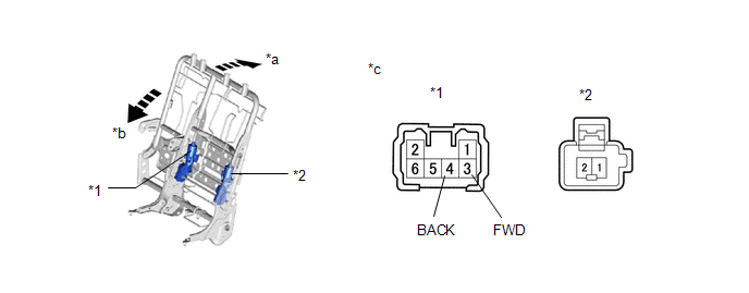
| *1 | Motor A | *2 | Motor B |
| *a | Forward | *b | Backward |
| *c | Component without wire harness connected (Rear Seatback Frame sub-assembly LH) | - | - |
OK:
| Condition | Specified Condition |
|---|---|
| Auxiliary battery positive (+) → Terminal 3 (FWD) (Motor A) Auxiliary battery negative (-) → Terminal 4 (BACK) (Motor A) | Forward |
| Auxiliary battery positive (+) → Terminal 1 (Motor B) Auxiliary battery negative (-) → Terminal 2 (Motor B) | |
| Auxiliary battery positive (+) → Terminal 4 (BACK) (Motor A) Auxiliary battery negative (-) → Terminal 3 (FWD) (Motor A) | Backward |
| Auxiliary battery positive (+) → Terminal 2 (Motor B) Auxiliary battery negative (-) → Terminal 1 (Motor B) |
If the result is not as specified, replace the rear seatback frame sub-assembly LH.
3. INSPECT REAR SEATBACK FRAME SUB-ASSEMBLY RH
(a) Check the operation of the reclining motor.
(1) Apply auxiliary battery voltage to the reclining motor connector, and check that the rear seatback frame sub-assembly RH operates smoothly as follows.
NOTICE:
- Connect the auxiliary battery simultaneously to motor A and motor B to perform an inspection.
- Do not apply voltage to terminals 2, 5 and 6 of the connector for motor A.
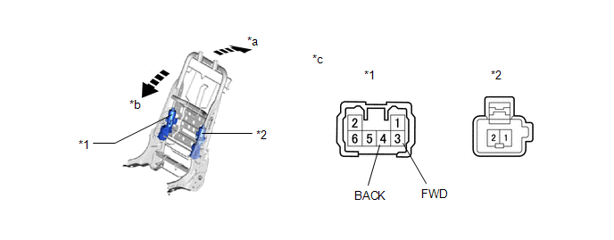
| *1 | Motor A | *2 | Motor B |
| *a | Forward | *b | Backward |
| *c | Component without wire harness connected (Rear Seatback Frame sub-assembly RH) | - | - |
OK:
| Condition | Specified Condition |
|---|---|
| Auxiliary battery positive (+) → Terminal 3 (FWD) (Motor A) Auxiliary battery negative (-) → Terminal 4 (BACK) (Motor A) | Forward |
| Auxiliary battery positive (+) → Terminal 1 (Motor B) Auxiliary battery negative (-) → Terminal 2 (Motor B) | |
| Auxiliary battery positive (+) → Terminal 4 (BACK) (Motor A) Auxiliary battery negative (-) → Terminal 3 (FWD) (Motor A) | Backward |
| Auxiliary battery positive (+) → Terminal 2 (Motor B) Auxiliary battery negative (-) → Terminal 1 (Motor B) |
If the result is not as specified, replace the rear seatback frame sub-assembly RH.
READ NEXT:
 Reassembly
REASSEMBLY CAUTION / NOTICE / HINT CAUTION: Wear protective gloves. Sharp areas on the parts may injure your hands. PROCEDURE 1. INSTALL REAR SEAT WIRE LH (for LH Side) (a) Attach the 2 clamps to i
Installation
INSTALLATION CAUTION / NOTICE / HINT CAUTION: Wear protective gloves. Sharp areas on the parts may injure your hands. PROCEDURE 1. INSTALL NO. 1 SEAT LEG ASSEMBLY (a) Attach the 2 guides to tempora
SEE MORE:
Open or Short in Steering Angle Sensor +B (C1625)
DESCRIPTION This DTC is stored if the parking assist ECU receives a signal via CAN communication from the steering sensor that indicates a power supply system problem. DTC No. Detection Item DTC Detection Condition Trouble Area C1625 Open or Short in Steering Angle Sensor +B Open or
Interior Light Auto Cut Circuit
DESCRIPTION The main body ECU (multiplex network body ECU) controls the DOME CUT relay. WIRING DIAGRAM CAUTION / NOTICE / HINT NOTICE:
Inspect the fuses for circuits related to this system before performing the following procedure.
Recognition code registration is necessary when replacing the
