Lexus NX: Inspection
INSPECTION
PROCEDURE
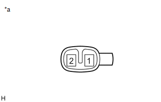
1. INSPECT SIDE TURN SIGNAL LIGHT ASSEMBLY LH
| (a) Apply auxiliary battery voltage to the connector and check the light illumination condition. OK:
If the result is not as specified, replace the side turn signal light assembly LH. |
|
2. INSPECT SIDE TURN SIGNAL LIGHT ASSEMBLY RH
| (a) Apply auxiliary battery voltage to the connector and check the light illumination condition. OK:
If the result is not as specified, replace the side turn signal light assembly RH. |
|
READ NEXT:
 Installation
INSTALLATION CAUTION / NOTICE / HINT HINT:
Use the same procedure for the RH and LH sides.
The procedure described below is for the LH side.
PROCEDURE 1. INSTALL SIDE TURN SIGNAL LIGHT ASSEMBL
Components
COMPONENTS ILLUSTRATION *1 COWL SIDE TRIM BOARD LH *2 DOOR SCUFF PLATE ASSEMBLY LH *3 INSTRUMENT SIDE PANEL LH *4 LOWER NO. 1 INSTRUMENT PANEL FINISH PANEL *5 NO. 1 INSTRUMEN
SEE MORE:
Wheels
If a wheel is bent, cracked or heavily
corroded, it should be replaced.
Otherwise, the tire may separate
from the wheel or cause a loss of
handling control.
Wheel selection
When replacing wheels, care should
be taken to ensure that they are equivalent
to those removed in load capacity,
di
Precaution
PRECAUTION HANDLING PRECAUTIONS FOR SRS AIRBAG SYSTEM (a) This vehicle is equipped with a Supplemental Restraint System (SRS). Failure to carry out service operations in the correct sequence could cause the SRS to unexpectedly deploy during servicing. This may cause a serious accident. Before servic
