Lexus NX: Inspection
Lexus NX Service Manual / Brake / Brake Control / Dynamic Control Systems / Brake Hold Switch / Inspection
INSPECTION
PROCEDURE
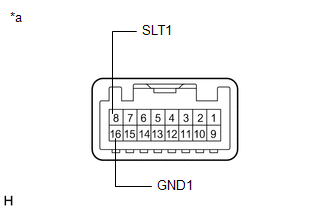
1. INSPECT INTEGRATION CONTROL AND PANEL ASSEMBLY (BRAKE HOLD SWITCH)
| (a) Measure the resistance according to the value(s) in the table below. Standard Resistance:
If the result is not as specified, replace the integration control and panel assembly (brake hold switch). |
|
READ NEXT:
 Installation
INSTALLATION PROCEDURE 1. INSTALL INTEGRATION CONTROL AND PANEL ASSEMBLY (BRAKE HOLD SWITCH) (a) Install the integration control and panel assembly (brake hold switch) to the upper rear console pan
Components
COMPONENTS ILLUSTRATION *A for Compact Spare Tire *B for Full Size Spare Tire *1 DECK FLOOR BOX LH *2 NO. 3 DECK BOARD SUB-ASSEMBLY *3 REAR DECK FLOOR BOX *4 NEGATIVE AUX
SEE MORE:
No Response from Steering Lock ECU (B2786)
DESCRIPTION This DTC is stored when LIN communication between the certification ECU (smart key ECU assembly) and steering lock actuator stops for 10 seconds or more. DTC No. Detection Item DTC Detection Condition Trouble Area B2786 No Response from Steering Lock ECU Communication be
Problem Symptoms Table
PROBLEM SYMPTOMS TABLE HINT:
If a problem occurs in certain locations or at certain times of day, check for the possibility of wave interference.
When the electrical key transmitter sub-assembly is brought near the door control receiver (RF band), door outside handle (LF band), indoor electrica
© 2016-2026 Copyright www.lexunx.com
