Lexus NX: Installation
INSTALLATION
PROCEDURE
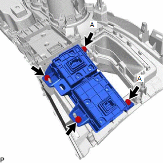
1. INSTALL INTEGRATION CONTROL AND PANEL ASSEMBLY (BRAKE HOLD SWITCH)
| (a) Install the integration control and panel assembly (brake hold switch) to the upper rear console panel sub-assembly with the 2 screws. HINT: The locations labeled A in the illustration are tightened together with the shift position indicator. |
|
2. INSTALL SHIFT POSITION INDICATOR
Click here .gif)
3. INSTALL REAR UPPER CONSOLE PANEL SUB-ASSEMBLY
Click here
4. INSTALL SHIFT LEVER KNOB SUB-ASSEMBLY
Click here
5. INSTALL CENTER INSTRUMENT CLUSTER FINISH PANEL ASSEMBLY
Click here
6. INSTALL NO. 2 INSTRUMENT PANEL SAFETY PAD SUB-ASSEMBLY
Click here
7. INSTALL INSTRUMENT SIDE PANEL RH
Click here
8. INSTALL NO. 1 SWITCH HOLE BASE
Click here
9. INSTALL LOWER NO. 1 INSTRUMENT PANEL FINISH PANEL
Click here
10. INSTALL NO. 1 INSTRUMENT PANEL UNDER COVER SUB-ASSEMBLY
Click here
11. INSTALL NO. 1 INSTRUMENT PANEL SAFETY PAD SUB-ASSEMBLY
Click here
12. INSTALL INSTRUMENT SIDE PANEL LH
Click here
13. INSTALL UPPER NO. 2 CONSOLE PANEL GARNISH
Click here
14. INSTALL UPPER NO. 1 CONSOLE PANEL GARNISH
Click here
15. INSTALL REAR UPPER CONSOLE PANEL
Click here
16. INSTALL CONSOLE ARMREST ASSEMBLY
Click here
READ NEXT:
 Components
COMPONENTS ILLUSTRATION *A for Compact Spare Tire *B for Full Size Spare Tire *1 DECK FLOOR BOX LH *2 NO. 3 DECK BOARD SUB-ASSEMBLY *3 REAR DECK FLOOR BOX *4 NEGATIVE AUX
Removal
REMOVAL CAUTION / NOTICE / HINT NOTICE: While the auxiliary battery is connected, even if the power switch is off, the brake control system activates when the brake pedal is depressed or any door cour
SEE MORE:
Removal
REMOVAL CAUTION / NOTICE / HINT NOTICE:
When the brake pedal is first depressed after replacing the brake pads or pushing back the disc brake piston, DTC C1214 may be output. As there is no malfunction, clear the DTC.
While the auxiliary battery is connected, even if the power switch is off, th
Precaution
PRECAUTION POWER WINDOW CONTROL SYSTEM PRECAUTIONS NOTICE:
The power window control system uses the LIN communication system and CAN communication system. Inspect the communication function by following How to Proceed with Troubleshooting. Troubleshoot the power window control system after confir
