Lexus NX: Inspection
INSPECTION
PROCEDURE
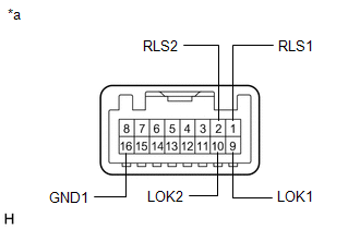
1. INSPECT INTEGRATION CONTROL AND PANEL ASSEMBLY (ELECTRIC PARKING BRAKE SWITCH)
| (a) Measure the resistance according to the value(s) in the table below. Standard Resistance:
If the result is not as specified, replace the integration control and panel assembly (electric parking brake switch). |
|
READ NEXT:
 Installation
INSTALLATION PROCEDURE 1. INSTALL INTEGRATION CONTROL AND PANEL ASSEMBLY (ELECTRIC PARKING BRAKE SWITCH) (a) Install the integration control and panel assembly (electric parking brake switch) to th
Precaution
PRECAUTION TROUBLESHOOTING PRECAUTIONS (a) When there is a malfunction with terminal contact points or a problem with the installation of a part, reconnecting the connectors or removal/installation of
SEE MORE:
Installation
INSTALLATION CAUTION / NOTICE / HINT NOTICE:
Always use a new grommet and valve core when installing the tire pressure warning valve and transmitter.
Check that the washer and nut are not damaged, and replace them if necessary.
Make sure not to damage the urethane covered backside of the tire
System Description
SYSTEM DESCRIPTION SYSTEM FUNCTION Function Outline Push-button start function When the electrical key transmitter sub-assembly is brought into the vehicle and verified, this function changes the power source or starts the hybrid control system when the power switch and brake pedal are op
