Lexus NX: Installation
INSTALLATION
PROCEDURE
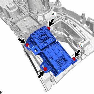
1. INSTALL INTEGRATION CONTROL AND PANEL ASSEMBLY (ABSORBER CONTROL SWITCH)
| (a) Install the integration control and panel assembly (absorber control switch) to the upper rear console panel sub-assembly with the 2 screws. HINT: The locations labeled A in the illustration are tightened together with the shift position indicator. |
|
2. INSTALL SHIFT POSITION INDICATOR
Click here .gif)
3. INSTALL UPPER REAR CONSOLE PANEL SUB-ASSEMBLY
Click here
4. INSTALL SHIFT LEVER KNOB SUB-ASSEMBLY
Click here
5. INSTALL CENTER INSTRUMENT CLUSTER FINISH PANEL ASSEMBLY
Click here
6. INSTALL NO. 2 INSTRUMENT PANEL SAFETY PAD SUB-ASSEMBLY
Click here
7. INSTALL INSTRUMENT SIDE PANEL RH
Click here
8. INSTALL NO. 1 SWITCH HOLE BASE
Click here
9. INSTALL LOWER NO. 1 INSTRUMENT PANEL FINISH PANEL
Click here
10. INSTALL NO. 1 INSTRUMENT PANEL UNDER COVER SUB-ASSEMBLY
Click here
11. INSTALL NO. 1 INSTRUMENT PANEL SAFETY PAD SUB-ASSEMBLY
Click here
12. INSTALL INSTRUMENT SIDE PANEL LH
Click here
13. INSTALL UPPER NO. 2 CONSOLE PANEL GARNISH
Click here
14. INSTALL UPPER NO. 1 CONSOLE PANEL GARNISH
Click here
15. INSTALL UPPER REAR CONSOLE PANEL
Click here
16. INSTALL CONSOLE ARMREST ASSEMBLY
Click here
READ NEXT:
 Precaution
PRECAUTION ADAPTIVE VARIABLE SUSPENSION SYSTEM PRECAUTION NOTICE:
Performing work after replacing the absorber control ECU with a normally functioning one from another vehicle may result in DTCs be
Parts Location
PARTS LOCATION ILLUSTRATION *1 FRONT ABSORBER CONTROL ACTUATOR RH (FRONT SHOCK ABSORBER ASSEMBLY RH) *2 FRONT ABSORBER CONTROL ACTUATOR LH (FRONT SHOCK ABSORBER ASSEMBLY LH) *3 REAR AB
SEE MORE:
Adjustment
ADJUSTMENT CAUTION / NOTICE / HINT HINT:
Use the same procedure for the RH and LH sides.
The procedure listed below is for the LH side.
It is possible that a headlight assembly is incorrectly installed, affecting headlight aim. Headlight assembly installation should be considered prior to per
Short in Motor Circuit (C1521-C1524,C1528,C1531-C1555)
DESCRIPTION The power steering ECU assembly detects steering force using the signal received from the steering torque sensor, and also monitors the motor circuit for errors. DTC No. Detection Item DTC Detection Condition Trouble Area Warning Indicate Return-to-normal Condition Note
