Lexus NX: Installation
INSTALLATION
CAUTION / NOTICE / HINT
HINT:
- Use the same procedure for the RH and LH sides.
- The procedure listed below is for the LH side.
PROCEDURE
1. INSTALL BACK DOOR LOWER DAMPER STAY BRACKET LH
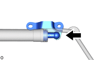
| (a) Perform this procedure when replacing only the back door lower damper stay bracket LH. (1) Install the joint. (2) Set the protector cover to the joint. (3) Set the power back door unit assembly to the joint. (4) Using a 3 mm pin punch and hammer, tap a new pin into the joint. (5) Return the protector cover to its original position and install the back door unit assembly set LH (spindle) to the back door lower damper stay bracket. |
|
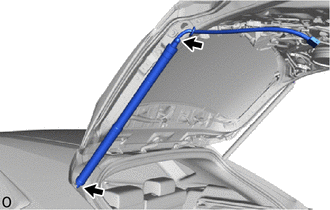
2. INSTALL POWER BACK DOOR UNIT ASSEMBLY SET LH
(a) Install a new power back door unit assembly set LH.
NOTICE:
The spindle unit and bracket cannot be disassembled once they have been assembled. Therefore, when replacing the spindle, upper bracket or lower bracket, make sure to replace the spindle, upper bracket and lower bracket as a set.
(1) When replacing the bolt with a new one:
- Clean the threaded portion on the vehicle body with non-residue solvent.
(2) When reusing the bolt:
- Clean the threaded portion on the vehicle body with non-residue solvent.
-
Apply adhesive to the threads of the 4 bolts.
Adhesive:
Toyota Genuine Adhesive 1324, Three Bond 1324 or equivalent
(3) Temporarily install a new back door upper damper stay bracket LH.
(4) Temporarily install a new back door lower damper stay bracket LH.
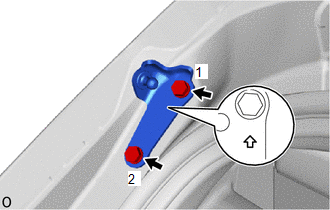
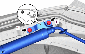
| (5) Tighten the 2 bolts to install the back door upper damper stay bracket LH. HINT: Tighten the bolts in the order shown in the illustration. Torque: 18 N·m {184 kgf·cm, 13 ft·lbf} |
|
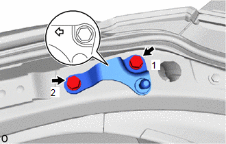
| (6) Tighten the 2 bolts to install the back door upper damper stay bracket LH. HINT: Tighten the bolts in the order shown in the illustration. Torque: 18 N·m {184 kgf·cm, 13 ft·lbf} |
|
| (7) Install the power back door unit assembly set LH (spindle). NOTICE:
|
|
(b) When reusing the power back door unit assembly set LH:
(1) When replacing the bolt with a new one:
- Clean the threaded portion on the vehicle body with non-residue solvent.
(2) When reusing the bolt:
- Clean the threaded portion on the vehicle body with non-residue solvent.
-
Apply adhesive to the threads of the 4 bolts.
Adhesive:
Toyota Genuine Adhesive 1324, Three Bond 1324 or equivalent
| (3) for Back Door Side:
HINT: Tighten the bolts in the order shown in the illustration. Torque: 18 N·m {184 kgf·cm, 13 ft·lbf} NOTICE:
|
|
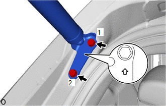
| (4) for Body Side:
HINT: Tighten the bolts in the order shown in the illustration. Torque: 18 N·m {184 kgf·cm, 13 ft·lbf} NOTICE:
|
|
(c) Attach the grommet and connect the harness.
(d) Connect the connector.
3. INSTALL BACK DOOR TRIM BOARD ASSEMBLY
Click here .gif)
4. INSTALL BACK DOOR LOCK COVER
Click here
5. INSTALL BACK DOOR TRIM BASE
Click here
6. INSTALL PULL HANDLE
Click here
7. INSTALL BACK DOOR SIDE GARNISH LH
Click here
8. INSTALL BACK DOOR SIDE GARNISH RH
Click here
9. INSTALL BACK DOOR CENTER GARNISH
Click here
READ NEXT:
 Power Back Door Main Switch
InspectionINSPECTION PROCEDURE 1. INSPECT POWER BACK DOOR MAIN SWITCH (a) Check the resistance. (1) Measure the resistance according to the value(s) in the table below. Standard Resistance: Te
Precaution
PRECAUTION PRECAUTIONS FOR HANDS FREE POWER BACK DOOR (w/ Hands Free Power Back Door) (a) In the following situations, the hands free power back door may operate unintentionally if the electrical tran
SEE MORE:
Inspection
INSPECTION PROCEDURE 1. INSPECT INTEGRATION CONTROL AND PANEL ASSEMBLY (ELECTRIC PARKING BRAKE SWITCH) (a) Measure the resistance according to the value(s) in the table below. Standard Resistance: Tester Connection Condition Specified Condition 9 (LOK1) -16 (GND1) OFF(Release) 97.
Linear Solenoid Valve Offset Learning undone (C1345,C1368)
DESCRIPTION The skid control ECU (brake booster with master cylinder assembly) stores and corrects the individual differences in the brake pedal stroke sensor assembly, actuator solenoids, and stroke simulator solenoid. Perform initialization and calibration of the linear solenoid valve if any of th
