Lexus NX: Installation
INSTALLATION
PROCEDURE
1. INSTALL RADIO SETTING CONDENSER
| (a) Attach the claw to install a new terminal cover to the wire harness. NOTICE:
|
|
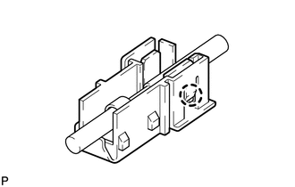
| (b) Attach the 6 claws to install 2 new terminal covers with wire harness to a new condenser. NOTICE:
|
|
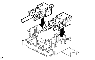
| (c) Insert the cover as shown in the illustration and attach the claw. |
|
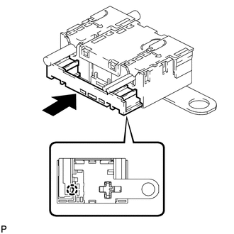
(d) Attach the clamp to temporarily install the radio setting condenser with wire harness.
(e) Install the radio setting condenser with the bolt.
Torque:
8.0 N·m {82 kgf·cm, 71 in·lbf}
2. INSTALL INNER ROOF SIDE GARNISH ASSEMBLY LH
Click here .gif)
3. INSTALL DECK TRIM SIDE PANEL ASSEMBLY LH
Click here
4. INSTALL NO. 1 LUGGAGE COMPARTMENT TRIM HOOK
Click here
5. INSTALL LUGGAGE HOLD BELT STRIKER ASSEMBLY
Click here
6. INSTALL ROPE HOOK ASSEMBLY
Click here
7. INSTALL UPPER DECK TRIM SIDE BOARD LH
Click here
8. INSTALL REAR DOOR OPENING TRIM WEATHERSTRIP LH
Click here
9. INSTALL REAR DOOR SCUFF PLATE LH
Click here
10. INSTALL REAR FLOOR FINISH PLATE
Click here
11. INSTALL NO. 2 TOOL BOX SUB-ASSEMBLY
Click here
12. INSTALL NO. 1 TOOL BOX SUB-ASSEMBLY
Click here
13. INSTALL DECK FLOOR BOX RH
Click here
14. INSTALL DECK FLOOR BOX LH
Click here
15. INSTALL SPARE TIRE
Click here
16. INSTALL REAR DECK FLOOR BOX
Click here
17. INSTALL NO. 3 DECK BOARD SUB-ASSEMBLY
Click here
18. INSTALL NO. 2 DECK BOARD SUB-ASSEMBLY
Click here
19. INSTALL DECK BOARD ASSEMBLY
Click here
20. INSTALL TONNEAU COVER ASSEMBLY
Click here
21. INSTALL REAR SEAT ASSEMBLY (for Power Seat)
Click here
22. INSTALL REAR SEAT ASSEMBLY (for Manual Seat)
Click here
READ NEXT:
 Components
COMPONENTS ILLUSTRATION *1 DECK BOARD ASSEMBLY *2 NO. 2 DECK BOARD SUB-ASSEMBLY *3 NO. 3 DECK BOARD SUB-ASSEMBLY *4 TONNEAU COVER ASSEMBLY ILLUSTRATION *1 DECK FLOOR BOX L
Removal
REMOVAL PROCEDURE 1. REMOVE REAR SEAT ASSEMBLY (for Manual Seat) Click here 2. REMOVE REAR SEAT ASSEMBLY (for Power Seat) Click here 3. REMOVE TONNEAU COVER ASSEMBLY Click here 4. REMOVE DECK B
SEE MORE:
Precaution
PRECAUTION HANDLING PRECAUTIONS FOR SRS AIRBAG SYSTEM Click here HANDLING PRECAUTIONS FOR STEERING COLUMN (a) When handling the electric power steering column sub-assembly: (1) Avoid any impact to the electric power steering column sub-assembly, especially to the motor or torque sensor. Replace t
Initialization has not been Performed (B2450)
DESCRIPTION The vehicle height must be initialized for the headlight ECU sub-assembly LH to perform auto leveling control. DTC No. Detection Item DTC Detection Condition Trouble Area B2450 Initialization has not been Performed
Power switch on (IG)
ECU initialization incompl
