Lexus NX: Removal
REMOVAL
PROCEDURE
1. REMOVE REAR SEAT ASSEMBLY (for Manual Seat)
Click here .gif)
2. REMOVE REAR SEAT ASSEMBLY (for Power Seat)
Click here
3. REMOVE TONNEAU COVER ASSEMBLY
Click here
4. REMOVE DECK BOARD ASSEMBLY
Click here
5. REMOVE NO. 2 DECK BOARD SUB-ASSEMBLY
Click here
6. REMOVE NO. 3 DECK BOARD SUB-ASSEMBLY
Click here
7. REMOVE REAR DECK FLOOR BOX
Click here
8. REMOVE SPARE TIRE
Click here
9. REMOVE DECK FLOOR BOX LH
Click here
10. REMOVE DECK FLOOR BOX RH
Click here
11. REMOVE NO. 1 TOOL BOX SUB-ASSEMBLY
Click here
12. REMOVE NO. 2 TOOL BOX SUB-ASSEMBLY
Click here
13. REMOVE REAR FLOOR FINISH PLATE
Click here
14. REMOVE REAR DOOR SCUFF PLATE LH
Click here
15. REMOVE REAR DOOR OPENING TRIM WEATHERSTRIP LH
Click here
16. REMOVE UPPER DECK TRIM SIDE BOARD LH
Click here
17. REMOVE ROPE HOOK ASSEMBLY
Click here
18. REMOVE LUGGAGE HOLD BELT STRIKER ASSEMBLY
Click here
19. REMOVE NO. 1 LUGGAGE COMPARTMENT TRIM HOOK
Click here
20. REMOVE DECK TRIM SIDE PANEL ASSEMBLY LH
Click here
21. REMOVE INNER ROOF SIDE GARNISH ASSEMBLY LH
Click here
22. REMOVE REAR HEADER SPEAKER ASSEMBLY
NOTICE:
Do not touch the cone part of the speaker.
| (a) Disconnect the connector. |
|
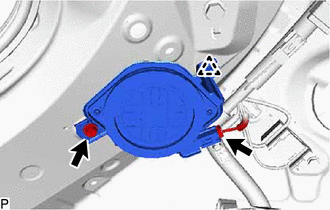
(b) Detach the clip and remove the bolt and rear header speaker assembly.
READ NEXT:
 Inspection
INSPECTION PROCEDURE 1. INSPECT REAR HEADER SPEAKER ASSEMBLY (a) Measure the resistance according to the value(s) in the table below. Standard Resistance: Tester Connection Condition Specif
Installation
INSTALLATION PROCEDURE 1. INSTALL REAR HEADER SPEAKER ASSEMBLY NOTICE: Do not touch the cone part of the speaker. (a) Temporarily install the speaker by attaching the clip of the speaker to the veh
SEE MORE:
"CHK" message(s) are displayed on the SIGNAL CHECK screen.
DESCRIPTION On the SIGNAL CHECK screen, it is possible to check if the signals sent to the parking assist ECU are normal. Click here HINT:
On the SIGNAL CHECK screen, "OK" (blue) is displayed for items with a normal inspection result or input state.
On the SIGNAL CHECK screen, "CHK" (red) is
Seat Heater Control (for Front Seat)
ComponentsCOMPONENTS ILLUSTRATION *A for L-Sport *B for F-Sport *1 SEAT HEATER CONTROL SUB-ASSEMBLY LH - - RemovalREMOVAL CAUTION / NOTICE / HINT CAUTION: Wear protective gloves. Sharp areas on the parts may injure your hands. HINT:
Use the same procedure for the RH and L
