Lexus NX: Installation
INSTALLATION
CAUTION / NOTICE / HINT
HINT:
- Use the same procedure for RHD and LHD vehicles.
- The procedures listed below are for LHD vehicles.
PROCEDURE
1. INSTALL LOWER NO. 1 INSTRUMENT PANEL AIRBAG ASSEMBLY
(a) Check that the power switch is off.
(b) Check that the cable is disconnected from the negative (-) auxiliary battery terminal.
CAUTION:
Wait at least 90 seconds after disconnecting the cable from the negative (-) auxiliary battery terminal to disable the SRS system.
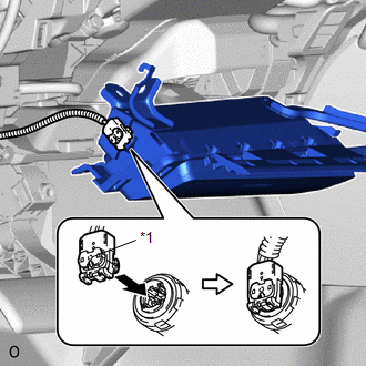
| (c) Connect the airbag connector and push in the connector lock. NOTICE: When connecting any airbag connector, take care not to damage the airbag wire harness. |
|
(d) Attach the 2 hooks to set the lower No. 1 instrument panel airbag assembly.
(e) Install the 4 bolts.
Torque:
10 N·m {102 kgf·cm, 7 ft·lbf}
NOTICE:
Confirm that the lower No. 1 instrument panel airbag assembly is installed securely without any excessive gaps and is not protruding outward.
2. INSTALL LOWER NO. 1 INSTRUMENT PANEL FINISH PANEL
Click here .gif)
3. INSTALL NO. 1 INSTRUMENT PANEL UNDER COVER SUB-ASSEMBLY
Click here
4. INSTALL UPPER NO. 2 CONSOLE PANEL GARNISH
Click here
5. INSTALL REAR CONSOLE ARMREST ASSEMBLY
Click here
6. INSTALL NO. 1 INSTRUMENT PANEL SAFETY PAD SUB-ASSEMBLY
Click here
7. INSTALL INSTRUMENT SIDE PANEL LH
Click here
8. INSTALL COWL SIDE TRIM BOARD LH
Click here
9. INSTALL DOOR SCUFF PLATE ASSEMBLY LH
Click here
10. CONNECT CABLE TO NEGATIVE AUXILIARY BATTERY TERMINAL
(a) Connect the cable to the negative (-) auxiliary battery terminal and tighten the nut.
Torque:
5.4 N·m {55 kgf·cm, 48 in·lbf}
11. INITIALIZATION AFTER RECONNECTING AUXILIARY BATTERY TERMINAL
Click here
HINT:
When disconnecting and reconnecting the auxiliary battery, there is an automatic learning function that completes learning when the respective system is used.
Click here
12. INSTALL DECK FLOOR BOX LH
Click here
13. INSTALL REAR DECK FLOOR BOX
Click here
14. INSTALL NO. 3 DECK BOARD SUB-ASSEMBLY
Click here
15. PERFORM DIAGNOSTIC SYSTEM CHECK
Click here
16. CHECK SRS WARNING LIGHT
Click here
READ NEXT:
 Disposal
DISPOSAL CAUTION / NOTICE / HINT CAUTION: Before performing pre-disposal deployment of any SRS part, review and closely follow all applicable environmental and hazardous material regulations. Pre-disp
Components
COMPONENTS ILLUSTRATION *1 DECK FLOOR BOX LH *2 NO. 3 DECK BOARD SUB-ASSEMBLY *3 REAR DECK FLOOR BOX *4 AUXILIARY BATTERY NEGATIVE TERMINAL N*m (kgf*cm, ft.*lbf): Specified
SEE MORE:
Removal
REMOVAL PROCEDURE 1. PRECAUTION (a) w/ Parking Assist Monitor System: Click here (b) w/ Panoramic View Monitor System: Click here 2. REMOVE BACK DOOR TRIM BASE (w/ Power Back Door) Click here 3. REMOVE PULL HANDLE (w/ Power Back Door) Click here 4. REMOVE BACK DOOR FINISH COVER LH (w/o Power
Cellular Phone Inspection
CAUTION / NOTICE / HINT HINT: If the operation of a cellular phone or the radio receiver assembly is requested, make sure to follow the instructions closely and perform the operation. PROCEDURE 1. CHECK USAGE CONDITION (a) Check that the vehicle and cellular phone meet the following conditi
