Lexus NX: Disposal
DISPOSAL
CAUTION / NOTICE / HINT
CAUTION:
Before performing pre-disposal deployment of any SRS part, review and closely follow all applicable environmental and hazardous material regulations. Pre-disposal deployment may be considered hazardous material treatment.
PROCEDURE
1. PRECAUTION
CAUTION:
- An airbag or pretensioner may be activated by static electricity. To prevent this, be sure to touch a metal surface with your bare hands to discharge static electricity before performing this procedure.
- Never dispose of a lower No. 1 instrument panel airbag assembly with an undeployed airbag.
- The airbag produces an exploding sound when it is deployed, so perform the operation outdoors and where it will not create a nuisance to nearby residents.
- When deploying the airbag, always use the specified SST (SRS Airbag Deployment Tool). Perform the operation in a place away from electrical noise.
- When deploying the airbag, perform the operation at least 10 m (32.8 ft.) away from the lower No. 1 instrument panel airbag assembly.
- The lower No. 1 instrument panel airbag assembly becomes extremely hot when the airbag is deployed, so do not touch it for at least 30 minutes after deployment.
- Use gloves and safety glasses when handling a lower No. 1 instrument panel airbag assembly with a deployed airbag.
- Do not apply water etc. to a lower No. 1 instrument panel airbag assembly with a deployed airbag.
- Always wash your hands with water after completing the operation.
HINT:
When scrapping a vehicle equipped with an SRS or disposing of the lower No. 1 instrument panel airbag assembly, be sure to deploy the airbag first in accordance with the procedure described below. If any abnormality occurs with the airbag deployment, contact the Service Dept. of TOYOTA MOTOR SALES, U.S.A., INC.
2. DISPOSE OF LOWER NO. 1 INSTRUMENT PANEL AIRBAG ASSEMBLY (When Installed in Vehicle)
NOTICE:
- When disposing of the lower No. 1 instrument panel airbag assembly, use an unneeded vehicle to deploy the airbag.
- Be sure to observe the following procedure when deploying the airbag.
HINT:
Prepare a battery as the power source to deploy the airbag.
| (a) Check the function of SST. Click here SST: 09082-00700 |
|
.png)
(b) Refer to Precaution.
Click here .gif)
(c) Remove the No. 3 deck board sub-assembly.
Click here
(d) Remove the rear deck floor box.
Click here
(e) Remove the deck floor box LH.
Click here
(f) Disconnect the cable from the auxiliary battery negative (-) terminal.
Click here
CAUTION:
Wait at least 90 seconds after disconnecting the cable from the auxiliary battery negative (-) terminal to disable the SRS system.
(g) Remove the lower No. 1 instrument panel airbag assembly.
Click here
(h) Install SST.
CAUTION:
Check that there is no looseness in the lower No. 1 instrument panel airbag assembly.
| (1) Connect the SST connector to the lower No. 1 instrument panel airbag assembly. SST: 09082-00700 SST: 09082-00802 09082-10801 09082-20801 NOTICE: To avoid damaging the SST connector or wire harness, do not lock the secondary lock of the twin lock. |
|
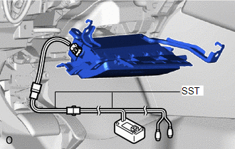
(2) Install the lower No. 1 instrument panel airbag assembly.
Click here
| (3) Move SST at least 10 m (32.8 ft.) away from the front side window of the vehicle. |
|
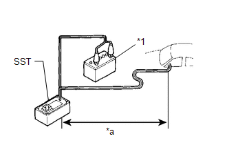
(4) While maintaining sufficient clearance for the SST wire harness in the front side window, close all doors and windows of the vehicle.
NOTICE:
Take care not to damage the SST wire harness.
(5) Connect the red clip of SST to the positive (+) battery terminal and the black clip of SST to the negative (-) battery terminal.
(i) Deploy the airbag.
(1) Check that no one is inside the vehicle or within a 10 m (32.8 ft.) radius of the vehicle.
(2) Press the SST activation switch and deploy the airbag.
CAUTION:
Before deployment, make sure that no one is near the vehicle.
HINT:
The airbag is deployed as the LED of the SST activation switch comes on.
(j) Remove the lower No. 1 instrument panel airbag assembly.
Click here
CAUTION:
- The lower No. 1 instrument panel airbag assembly becomes extremely hot when the airbag is deployed, so do not touch it for at least 30 minutes after deployment.
- Use gloves and safety glasses when handling a lower No. 1 instrument panel airbag assembly with a deployed airbag.
- Do not apply water etc. to a lower No. 1 instrument panel airbag assembly with a deployed airbag.
- After removal, quickly seal the lower No. 1 instrument panel airbag assembly in a plastic bag.
- Always wash your hands with water after completing the operation.
(k) Place the lower No. 1 instrument panel airbag assembly in a plastic bag, tie it tightly and dispose of it according to local regulations.
3. DISPOSE OF LOWER NO. 1 INSTRUMENT PANEL AIRBAG ASSEMBLY (When not Installed in Vehicle)
NOTICE:
Be sure to observe the following procedure when deploying the airbag.
HINT:
Prepare a battery as the power source to deploy the airbag.
| (a) Check the function of SST. Click here SST: 09082-00700 |
|
(b) Remove the lower No. 1 instrument panel airbag assembly.
Click here
CAUTION:
- Before removing the lower No. 1 instrument panel airbag assembly, wait at least 90 seconds after turning the power switch off and disconnecting the cable from the auxiliary battery negative (-) terminal.
- When storing the lower No. 1 instrument panel airbag assembly, keep the airbag deployment side facing upward.
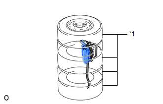
(c) Using braided wire, tie down the lower No. 1 instrument panel airbag assembly to an unneeded tire.
Wire:
Cross-sectional area of stripped wire
1.25 mm2 (0.0019 in.2) or more
CAUTION:
If the wire harness is too thin or an alternative object is used to tie down the lower No. 1 instrument panel airbag assembly, it may snap when the airbag is deployed. Always use a wire for vehicle use with an area of at least 1.25 mm2 (0.0019 in.2).
.png)
| *a | Wire Diameter |
| *b | Stripped Wire Section |
HINT:
To calculate the area of the cross-sectional area of stripped wire:
Area = 3.14 x (Diameter)2 / 4
(1) Position the lower No. 1 instrument panel airbag assembly inside the tire with the airbag deployment side facing inside.
Minimum tire size:
Must exceed the following dimensions
Width
185 mm (7.28 in.)
Inner diameter
360 mm (1.18 ft.)
CAUTION:
- Make sure that the wires are tight. If there is slack in the wires, the lower No. 1 instrument panel airbag assembly may break loose when the airbag is deployed.
- Always tie down the lower No. 1 instrument panel airbag assembly with the airbag deployment side facing inside the tire as shown in the illustration.
NOTICE:
The tires may be damaged by the airbag deployment, so use unneeded tires.
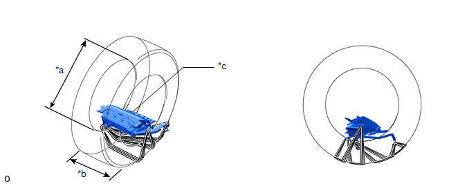
| *a | Inner Diameter | *b | Width |
| *c | Deployment Side | - | - |
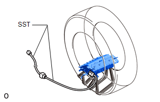
(d) Install SST.
| (1) After connecting the following SST to each other, connect them to the lower No. 1 instrument panel airbag assembly. SST: 09082-00802 09082-10801 09082-20801 |
|
(e) Place the tires.
| (1) Place at least 2 tires under the tire to which the lower No. 1 instrument panel airbag assembly is tied. |
|
(2) Place at least 2 tires onto the tire to which the lower No. 1 instrument panel airbag assembly is tied. The top tire should have a wheel installed.
NOTICE:
- Do not place the SST connector under the tire because it could be damaged.
- The tires and wheel may be damaged by the airbag deployment, so use unneeded tires and wheels.
| (3) Tie the tires together with the 2 wires. CAUTION: Make sure that the wires are tight. Looseness in the wires results in the tires breaking loose when the airbag is deployed. |
|
.png)
(f) Install SST.
| (1) Connect the SST connector. SST: 09082-00700 NOTICE: To avoid damaging the SST connector or wire harness, do not lock the secondary lock of the twin lock. Also, secure some slack for the SST wire harness inside the tire. |
|
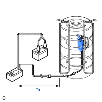
(2) Move SST at least 10 m (32.8 ft.) away from the airbag tied down to the tire.
(g) Deploy the airbag.
(1) Connect the red clip of SST to the positive (+) battery terminal and the black clip of SST to the negative (-) battery terminal.
(2) Check that no one is within a 10 m (32.8 ft.) radius of the wheel to which the lower No. 1 instrument panel airbag assembly is tied.
(3) Press the SST activation switch and deploy the airbag.
CAUTION:
Before deployment, make sure that no one is near the airbag.
HINT:
The airbag is deployed as the LED of the SST activation switch comes on.
(h) Dispose of the lower No. 1 instrument panel airbag assembly.
CAUTION:
- The lower No. 1 instrument panel airbag assembly becomes extremely hot when the airbag is deployed, so do not touch it for at least 30 minutes after deployment.
- Use gloves and safety glasses when handling a lower No. 1 instrument panel airbag assembly with a deployed airbag.
- Do not apply water etc. to a lower No. 1 instrument panel airbag assembly with a deployed airbag.
- Always wash your hands with water after completing the operation.
(1) Remove the lower No. 1 instrument panel airbag assembly from the wheel.
(2) Place the lower No. 1 instrument panel airbag assembly in a plastic bag, tie it tightly and dispose of it according to local regulations.
READ NEXT:
 Components
COMPONENTS ILLUSTRATION *1 DECK FLOOR BOX LH *2 NO. 3 DECK BOARD SUB-ASSEMBLY *3 REAR DECK FLOOR BOX *4 AUXILIARY BATTERY NEGATIVE TERMINAL N*m (kgf*cm, ft.*lbf): Specified
On-vehicle Inspection
ON-VEHICLE INSPECTION CAUTION / NOTICE / HINT CAUTION: Be sure to follow the correct removal and installation procedures of the occupant classification ECU. PROCEDURE 1. INSPECT OCCUPANT DETECTION ECU
SEE MORE:
Parts Location
PARTS LOCATION ILLUSTRATION *1 NO. 2 COMBINATION SWITCH ASSEMBLY - STEERING HEATER SWITCH *2 STEERING WHEEL ASSEMBLY - STEERING WHEEL HEATER UNIT *3 INSTRUMENT PANEL JUNCTION BLOCK ASSEMBLY - ECU-IG NO. 2 FUSE - ECU-IG NO. 3 FUSE *4 STEERING VIBRATION AND HEATER ECU *5 SPIR
System Diagram
SYSTEM DIAGRAM Communication Table Transmitter Receiver Signal Communication Method Multi-display Assembly Radio Receiver Assembly Windshield deicer switch signal GVIF Radio Receiver Assembly Air Conditioning Amplifier Assembly Windshield deicer switch signal CAN
