Lexus NX: Installation
INSTALLATION
CAUTION / NOTICE / HINT
NOTICE:
- When the brake pedal is first depressed after replacing the brake pads or pushing back the disc brake piston, DTC C1214 may be output. As there is no malfunction, clear the DTC.
- While the auxiliary battery is connected, even if the power switch is off, the brake control system activates when the brake pedal is depressed or the door courtesy switch is turned on. Therefore, even if only brake shoes are to be removed and installed, be sure to perform the Disable Brake Control procedure and disconnect the cable from the negative (-) terminal of the auxiliary battery before beginning work.
HINT:
- Use the same procedure for the RH and LH sides.
- The procedure listed below is for the LH side.
PROCEDURE
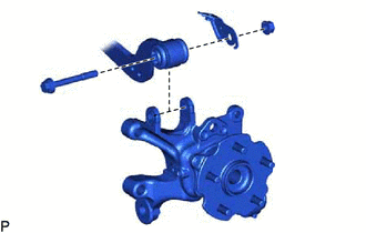
1. INSTALL REAR AXLE CARRIER SUB-ASSEMBLY LH
| (a) Temporarily install the rear axle carrier to the rear upper control arm with the bolt, parking brake wire bracket and nut. |
|
2. TEMPORARILY INSTALL REAR NO. 2 SUSPENSION ARM ASSEMBLY LH
(a) Install the rear lower coil spring insulator to the rear No. 2 suspension arm.
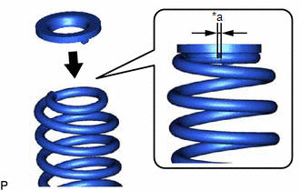
| (b) Install the rear upper coil spring insulator to the rear coil spring. NOTICE: Install the rear upper coil insulator so that the distance between the stopper and upper end of the rear coil spring is 10 mm (0.394 in.) or less. |
|
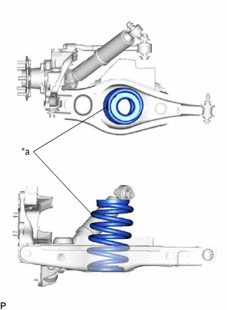
| (c) Install the rear coil spring to the rear No. 2 suspension arm. NOTICE: Make sure that the identification mark is positioned towards the outer sides of the vehicle. |
|
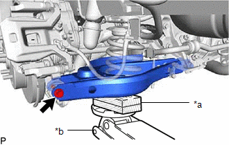
| (d) Using a jack and wooden block, raise the vehicle gradually to install the rear No. 2 suspension arm to the rear axle carrier. Then temporarily install the bolt. NOTICE:
|
|
3. INSTALL REAR TRAILING ARM ASSEMBLY
(a) Install the rear trailing arm to the axle carrier with the 2 bolts.
Torque:
200 N·m {2039 kgf·cm, 148 ft·lbf}
4. INSTALL REAR NO. 1 SUSPENSION ARM ASSEMBLY LH
(a) Install the rear No. 1 suspension arm to the rear axle carrier with a new nut.
Torque:
100 N·m {1020 kgf·cm, 74 ft·lbf}
5. INSTALL REAR NO. 1 SHOCK ABSORBER BRACKET LH
(a) Install the rear shock absorber bracket to the rear axle carrier with the 2 bolts.
Torque:
83 N·m {846 kgf·cm, 61 ft·lbf}
6. INSTALL REAR HEIGHT CONTROL SENSOR SUB-ASSEMBLY LH
Click here .gif)
7. STABILIZE SUSPENSION
Click here
8. TIGHTEN REAR UPPER CONTROL ARM ASSEMBLY LH
(a) Tighten the bolt.
Torque:
90 N·m {918 kgf·cm, 66 ft·lbf}
NOTICE:
Since a stopper nut is used, tighten the bolt.
9. TIGHTEN REAR NO. 2 SUSPENSION ARM ASSEMBLY LH
(a) Tighten the bolts of the suspension arm.
Torque:
90 N·m {918 kgf·cm, 66 ft·lbf}
10. CONNECT PARKING BRAKE WIRE ASSEMBLY NO.1
Click here
11. INSTALL REAR STABILIZER LINK ASSEMBLY LH
Click here
12. INSTALL REAR AXLE HUB AND BEARING ASSEMBLY LH
Click here
13. INSTALL REAR DISC
Click here
14. CONNECT REAR DISC BRAKE CALIPER ASSEMBLY LH
Click here
15. TEMPORARILY INSTALL REAR AXLE SHAFT NUT LH
Click here
16. INSPECT REAR AXLE HUB BEARING LOOSENESS
Click here
17. INSPECT REAR AXLE HUB RUNOUT
Click here
18. CONNECT REAR SPEED SENSOR LH
(a) w/ AVS:
Click here
(b) w/o AVS:
Click here
19. STAKE REAR AXLE SHAFT NUT LH
Click here
20. INSTALL REAR SUSPENSION ARM COVER LH
Click here
21. INSTALL REAR WHEEL
Click here
22. INSPECT AND ADJUST REAR WHEEL ALIGNMENT
Click here
23. CHECK FOR SPEED SENSOR SIGNAL
Click here
24. CONNECT CABLE TO NEGATIVE AUXILIARY BATTERY TERMINAL
(a) Connect the cable to the negative (-) auxiliary battery terminal and tighten the nut.
Torque:
5.4 N·m {55 kgf·cm, 48 in·lbf}
25. INITIALIZATION AFTER RECONECTING AUXILIARY BATTERY TERMINAL
Click here
HINT:
When disconnecting and reconnecting the auxiliary battery, there is an automatic learning function that completes learning when the respective system is used.
Click here
READ NEXT:
 Components
COMPONENTS ILLUSTRATION *A w/ AVS - - *1 REAR AXLE HUB AND BEARING ASSEMBLY LH *2 REAR AXLE SHAFT NUT LH *3 REAR DISC *4 REAR DISC BRAKE CALIPER ASSEMBLY LH *5 REAR
On-vehicle Inspection
ON-VEHICLE INSPECTION CAUTION / NOTICE / HINT NOTICE:
When the brake pedal is first depressed after replacing the brake pads or pushing back the disc brake piston, DTC C1214 may be output. As there
SEE MORE:
Removal
REMOVAL PROCEDURE 1. REMOVE CONSOLE BOX ASSEMBLY Click here 2. REMOVE DOOR SCUFF PLATE ASSEMBLY LH Click here 3. REMOVE COWL SIDE TRIM BOARD LH Click here 4. DISCONNECT FRONT FLOOR CARPET ASSEMBLY (a) Using a clip remover, remove the clip. *1 Hook *2 Fastener
Drive Motor "A" Inverter Voltage Sensor Circuit Range / Performance (P0D2E-565)
DTC SUMMARY MALFUNCTION DESCRIPTION VH voltage sensor signal malfunction in the inverter for the motor. Internal inverter malfunction
Internal circuit malfunction in the inverter for the motor
Malfunction in the sensors for inverter control (current sensor, voltage sensors (VH, VL), etc.)
DE
